Mechanical or Metallurgical Failure Mechanisms
885°F (475°C) Embrittlement
885 embrittlement a form of embrittlement that occurs from 600°F to 1000°F, but most readily at a temperature of 885°F, hence the name. Affected materials include 400 series of stainless steels, duplex stainless steels, and less commonly in some 300 series stainless steels containing a metallurgical phase called ferrite. This damage mechanism can occur in any unit where susceptible alloys are exposed to the embrittling temperature range.
885 embrittlement is not easily detected or reported before failure. It can be confirmed through bend or impact testing. Hardness tests that identify an increase in hardness in affected areas may also give indications of 885 embrittlement.
This failure can be avoided by choosing the right materials for pressure equipment. However, some types of trays and other non-pressure containing hardware may be constructed of susceptible alloys and end up cracking during repair or maintenance activities.
Image Gallery
Brittle Fracture
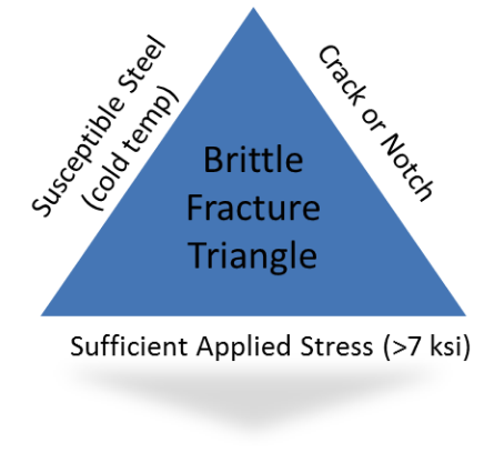
Brittle fracture is the sudden, very rapid fracture under residual and/or applied stress where the material exhibits little or no evidence of ductility or plastic degradation. Unlike most tensile failures, where the material plastically strains under overload conditions and becomes thinner at the point of rupture, when a piece of equipment suffers a brittle fracture, there is no thinning or necking down. Rather, it breaks “like glass” without a warning, and may in fact fracture into many pieces.
There are a number of key factors that combine to give rise to susceptibility to brittle fracture. One of the most important factors is temperature. If the steel temperature is below its brittle-to-ductile transition temperature, then it will be susceptible to brittle fracture. Combined with a critical sized flaw and high stress on that flaw (either applied or residual), then brittle fracture is likely.
The most susceptible materials are carbon and low alloy steels, but also include the 400 series martensitic steels such as the 12 Cr varieties.
Affected units or equipment:
- Equipment manufactured prior to the December 1987 ASME Section VIII, Div.1 code are susceptible.
- Most processes run at elevated temperatures, so the main concern for brittle fracture is during startup, shutdown, and hydrotesting.
- Thick walled vessels should be considered.
- Brittle fracture can also occur during auto-refrigeration.
Brittle fracture is best prevented by using materials specifically designed for low temperature operation including upset and auto-refrigeration events.
In existing equipment, preventative measures are limited to controlling operating conditions, minimizing pressure at ambient temperatures during startup and shutdown, and period inspection at high stress locations.
Inspection is not normally used to mitigate brittle fractures. Susceptible vessels should be inspected for pre-existing flaws and defects.
Image Gallery
Cavitation
Cavitation is the sudden formation and immediate collapse of vapor or air bubbles in a liquid stream when system pressure falls below the vapor pressure of the liquid. The sudden collapse of these tiny bubbles generates enormous, though tiny forces that mechanically erode metal. It affects copper, brass, cast iron, carbon steel, low alloy steels, 300 and 400 series stainless steels. It occurs in pumps and piping that are located downstream of orifices or control valves, and it can be found in some restricted-flow passages.
Cavitation is characterized by sharp-edged pitting, but may also have a gouged appearance in rotational components. Damage only occurs in localized low-pressure zones.
Typically, the noise generated by cavitation is easily detectable and often sounds like stones rattling around in a pump or valve. The key to mitigation of cavitation is for operators to report such noise to engineers and inspectors so that steps can be taken to mitigate the cause of cavitation.
As such, it is important for engineers and inspectors to let operators and maintenance personnel know about cavitation and how damaging it can be if it is not prevented.
In terms of inspection, acoustic monitoring of turbulent areas can be used to detect characteristic sound frequencies. Visual inspection, UT, and RT can be used to monitor for loss in thickness.
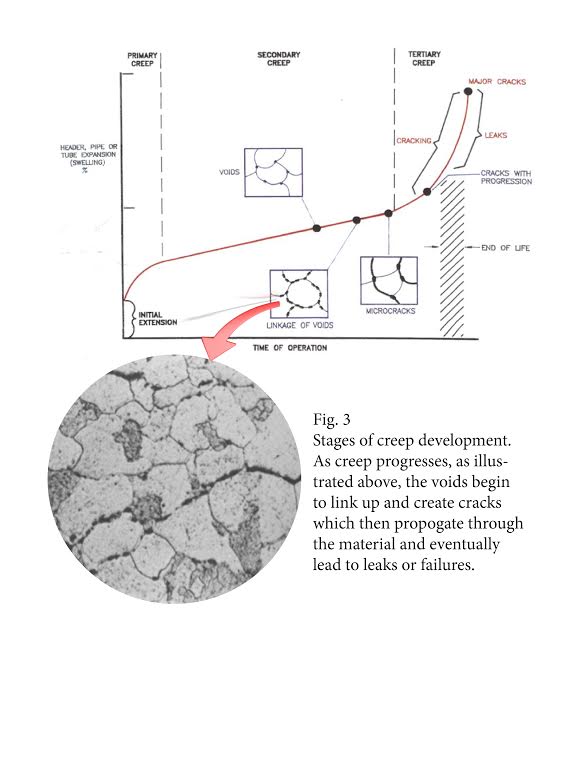
Creep and Stress Rupture
At high temperatures, metal slowly and continuously deforms under load. This deformation is known as creep. The rate at which a material will creep is dependent upon its strength, the stress imposed, and the operating temperature.
All metals and alloys are affected. The following table provides threshold temperatures for various materials:
| Material | Threshold Temperature |
| Carbon Steel | 650 F (343 C) |
| C-0.5 Mo | 700 F (371 C) |
| 1.25 Cr-0.5 Mo | 700 F (371 C) |
| 2.25 Cr | 750 F (399 C) |
| 5 Cr | 800 F (427 C) |
| 9 Cr | 800 F (427 C) |
| 304 SS | 800 F (427 C) |
Nozzles and other components with high tri-axial loading on some catalytic reformers have been susceptible to creep cracking and low creep ductility. While furnace components, e.g. tubes, supports, hangers, etc. most commonly experience creep damage, “cold-shell” designed equipment that is normally protected by refractory can suffer “surprise” creep damage when the refractory protection deteriorates. Dissimilar metal welds (DMW) are also susceptible to creep damage (e.g. ferritic to austenitic welds) because of the high localized stresses generated by differential thermal expansion.
The initial stages of creep can only be identified with a scanning electron microscope (SEM). At temperatures well above the creep threshold, noticeable deformation may be observed.
Since creep damage is irreversible, it is important to prevent it from occurring in the first place by establishing adequate IOWs for any components operating in the creep range, whereby operators should be required to make adjustments if certain temperatures are reached.
Austenitic stainless steels, especially the “H” grades, may provide greater creep resistance.
Inspection for creep damage requires a combination of techniques (UT, RT, EC, dimensional measurements and replication). Destructive sampling and metallographic examinations are used to confirm damage.
Image Gallery
Dissimilar Metal Weld Cracking
Dissimilar Metal Weld (DMW) Cracking is a fabrication issue that occurs at the weld juncture where carbon steel or low alloy steels are welded to austenitic (300 series) stainless steels in high temperature applications. The most common materials are ferritic steels (carbon steel and low alloy) that are welded to austenitic stainless steel. Any material combinations that have widely differing thermal expansion coefficients may be afflicted.
This type of cracking is most common when temperatures above 800F (425C) are involved, such as FCCU reactor/regeneration systems, superheaters, reheaters, fired heaters, and hydroprocess equipment.
Cracks form at the toe of the weld in the HAZ of the ferritic material.
The use of bolted joints, if possible, or nickel base filler materials helps to avoid the DMW cracking problem.
Before critical dissimilar butt welds are put into service, consider 100% PT after buttering and completion, 100% UT on the butter layer after PWHT, 100% RT, 100% UT, and Positive Materials Identification.
RT and UT shear wave inspection should be performed on dissimilar welds in fired heater tubes.
Surface breaking cracks on the ID surface can be detected using WFMT or external SWUT.
Erosion/Erosion-Corrosion
The combination of erosion and corrosion on a metal surface, which is caused by the rapid flow of turbulent liquids through piping, leads to Erosion-Corrosion. Turbulence is often caused by pitting.
This damage mechanism occurs due to the speed of a moving liquid, as well as its own corrosive properties. All metals, alloys, and refractories are affected. In fact, all types of equipment exposed to moving fluids are subject to erosion and erosion-corrosion.
The appearance of this damage mechanism comes in the form of pits, grooves, gullies, waves, rounded holes, and valleys. These localized losses of thickness often exhibit a directional pattern.
Erosion-Corrosion can be mitigated by reducing turbulence by streamlining piping or slowing the speed of the liquid. Corrosion inhibitors or cathodic protection may also be effective.
Visual examination of troublesome areas, as well as UT or RT can be used to detect the extent of metal loss. Specialized corrosion coupons and on-line corrosion monitoring electrical resistance probes have been used in some applications. IR scans are used to detect refractory loss on stream.
Gaseous Oxygen-Enhanced Ignition and Combustion
Metals burn in enriched air (having greater than 25% oxygen). Spontaneous oxygen fires may suddenly occur in such conditions, resulting in fires and explosions.
Carbon steel and low alloy steels are flammable above 15 psig (0.103 Mpa). Austenitic stainless steel can be used up to about 200 psig (1.38 Mpa). Cu alloys (greater than 55% Cu) are very resistant, as is Alloy 400. Aluminum can be used, but should be avoided because it burns quickly.
The easiest materials to ignite are plastics, rubber, and lubricants.
Any unit that uses oxygen or enriched air for combustion or other process reasons is affected. These include Sulfur Recovery Units, Fluid Catalytic Cracking Units, Gasification Units, and Partial Oxidation Units, among others.
To find signs of this damage mechanism, one should look for external heat damage such as glowing pipe or heat tint. No inspection method will reliably detect this sort of ignition/combustion.
In terms of mitigation, oxygen fires are not progressive or slowly-developing; they occur very quickly. It is recommended to refer to the industry recommended guidelines found in API RP 571 in order to learn the most effective prevention and mitigation strategies.
Graphitization
Graphitization is not something that operators can do much about, and thankfully it is not very common. It occurs when the microstructure of some grades of carbon steel and low alloy steels breaks down after long exposure to elevated temperatures, like in FCCUs. The carbide phases break down in temperature ranges from 825 to 1300 F (440 - 590 C) and cause the metal to weaken and be susceptible to cracking failures.
Graphitization damage is not visible and can only be observed with metallographic examination. Mitigating graphitization begins with the proper material selection is key to avoiding graphitization failures. Inspecting for graphitization includes conducting a metallographic analysis of coupons cut from the walls of susceptible equipment. This is effective in determining if graphitization may be occurring.
Mechanical Fatigue
| Foundational Concepts |
| Fatigue |
Mechanical fatigue (often referred to as “fatigue cracking”) is degradation that occurs when a piece of equipment is exposed to cyclical stress for an extended period of time. These stresses can arise from mechanical loading or thermal cycling. Fatigue cracking can be thought of as an “overuse” of a part, resulting in a break.
All alloys are affected, but stress levels and number of cycles required to cause failure vary by material. Equipment that is affected by thermal cycling (e.g., coke drums or auxiliary boilers) and equipment that is affected by mechanical loading (e.g., pressure swing adsorbers, rotating shafts on centrifugal pumps.).
The best defense against fatigue cracking is good design that helps minimize stress concentration of components that are in cyclic service. Fatigue cracks can be detected with NDE techniques such as PT, MT, and SWUT. Visual testing of small diameter piping can detect oscillation or other cyclical movements. Vibration monitoring of rotating equipment may be used to detect shafts that are out of balance.
Reheat Cracking
Reheat cracking (sometimes referred to as “stress relief cracking” or “stress relaxation cracking”) is intergranular cracking that occurs in the heat affected zone (HAZ) of welds or in the weld metal itself. Reheat cracking can either occur during PWHT or in service at high temperature.
This damage mechanism is most likely to occur in heavy wall vessels in areas of high restraint (e.g., nozzle welds and heavy wall piping). HSLA steels are very susceptible to reheat cracking.
Refractory Degradation
Refractories are used extensively in various units and processes. Refractory materials such as insulating ceramic fibers, castables, refractory brick, and plastic refractory, are susceptible to various forms of mechanical damage and corrosion.
The key to mitigating refractory damage is the proper selection of refractory, anchors, and fillers; as well as their proper installation. Inspecting for refractory damage consists of performing visual inspection during shutdowns. Furthermore, cold-wall equipment can be surveyed on-stream using IR to monitor for hot spots.
Short Term Overheating – Stress Rupture
Short Term Overheating (also referred to as Stress Rupture) occurs when equipment, piping or furnace tubes that are designed to operate safely and reliably in one temperature range are exposed to higher temperatures. At the higher temperatures the metal is weaker and can only resist operating pressures and stresses for a shorter period of time, sometimes only hours or minutes, if the design temperature is significantly exceeded. Furnace tubes are the most common types of equipment to suffer stress rupture from short term overheating.
Short Term Overheating can be prevented with careful operation, instrumentation, inspection, and maintenance activities. These include routine IR monitoring of susceptible equipment, heat sensitive paint on cold shell vessels, furnace tube and vessel skin thermocouples, careful burner management of fired heaters, and routine inspection and maintenance of refractory-lined equipment.
Sigma Phase Embrittlement
A metallurgical phase change occurs in some stainless steels when they are heated above about 1000F (540C). That phase change results in a dramatic loss of toughness, and therefore, can lead to brittle fracture of the “sigmatized” equipment.
There’s no reasonable way to detect sigmatized stainless steels other than doing impact testing or metallographic examination on failed equipment to verify what caused the brittle cracking. The key to prevention of brittle cracking from sigma phase is to select alloys that have less susceptibility to being sigmatized above 1000F, and with austenitic stainless steels that means careful ferrite control.
Softening (Spheroidization)
Spheroidization occurs when carbon and low alloy steels are exposed to temperatures in the range of 850F - 1400F (440C - 760C) where carbide phases (the strengthening element of steels) become unstable and begin to agglomerate, which then results in the loss of strength. It is not much of a threat to pressure equipment, except in some unusual circumstances. Usually the loss of strength is relatively minor, but under some high temperature conditions can cause a 30% reduction in strength. However, that loss of strength usually results in some reduction in design margin, which can sometimes be acceptable for continued safe operation with appropriate fitness-for-service analysis.
Equipment that is susceptible to spheroidization include most vessels or piping operating in the susceptible temperature range or that might be inadvertently exposed to high temperatures because of operating malfunctions. Such equipment includes furnace tubes, reactor/regeneration equipment in FCCUs, cat reformers, cokers and hydroprocess reactors that might be exposed to uncontrolled exothermic conditions (i.e.temperature runaways). Some steels are more susceptible than others, including fine-grained steels versus course-grained, aluminum-killed steels versus silicon-killed, and normalized steels versus annealed.
Though the likelihood of spheroidization damage can be detected with standard hardness testing looking for characteristic softening, spheroidization can only be confirmed by taking samples for laboratory metallography or performing field replication metallography for observation under microscopes.
Steam Blanketing
Steam-generating units, including fired boilers, waste heat exchangers in sulfur plants, hydrogen reformers, and FCC units, can be affected by this type of damage. Heat energy flowing through the wall of generating tubes results in the formation of steam bubbles, which are swept away by moving fluid. When the heat flow balance is disturbed, individual bubbles join to form a steam blanket. Once the steam blanket forms, tube rupture can occur rapidly.
Prevention can be achieved with proper burner management and proper Boiler Feed Water (BFW) treatment.
Strain Aging
Strain aging occurs mostly in older vintage steels (carbon and low alloy) that were common in older refineries. Decades ago, carbon steels were commonly manufactured using processes that contained higher levels of critical impurity elements than modern day steels, which are crafted with the Basic Oxygen Furnace (BOF) process. Steels made by BOF that are fully killed are not generally susceptible to Strain Aging.
What happens to the older steels is that they can undergo a form of precipitation-hardening which increases their strength a bit, but more importantly results in lower toughness. The lower toughness, in turn, could lead to brittle fracture when associated with a critical defect of some sort.
Temper Embrittlement
Temper embrittlement is a form of metallurgical degradation resulting from exposure of susceptible low alloy steels to higher temperature ranges, usually in service, but can occur to some extent even during heat treatment. Over a long period of exposure to high temperatures, the material’s ductile/brittle transition temperature decreases, meaning that it may become brittle at a lower temperature.
If significant temper embrittlement has occurred, the equipment may be susceptible to catastrophic brittle fracture. The low alloy steel most susceptible is the 2.25Cr-1Mo steel, from which so much of the refining industry’s heavy wall hydroprocess equipment is fabricated.
Certain low levels of “tramp” elements enhance the potential for temper embrittlement. These elements, which include phosphorus, tin, antimony, and arsenic, inadvertently make their way into steel during the steel making process or through welding.
The best way to minimize the likelihood and extent of the so-called “tramp” elements found in the base metal and welding consumables.
Temper embrittlement cannot be detected by normal inspection methods. Toughness testing is the only conclusive way of determining the extent of embrittlement.
Thermal Fatigue
| Foundational Concepts |
| Fatigue |
Thermal Fatigue is caused by swings in temperature that create cyclic stresses. In other words, repeated rises and falls in temperature of a component can result in cracking damage. The more dramatic the temperature swings, and the more frequent the number of cycles, the more likely that this damage mechanism will result.
Some examples of situations that may give rise to thermal fatigue are:
- Equipment startup and shutdown
- Mix points of hot and cold streams such as hydrogen mix points in hydroprocessing units
- Coke drum skirts, where stresses are promoted by a variation in temperature between the drum and skirt
Thermal Shock
| Foundational Concepts |
| Fatigue |
Thermal shock is a form of thermal fatigue cracking that can occur when high and non-uniform thermal stresses develop over a relatively short period of time in a piece of equipment.
Thermal shock failures usually involve sudden quenching of high temperature equipment and furnace tubes with a relatively cooler liquid or saturated steam containing some liquid, but not always. It can occur from sudden cooling of any high temperature equipment, or sudden cooling of even lower temperature equipment that causes it to suddenly be operating in a range in which it is now brittle. Physical restraint of equipment that needs to grow as its temperature increases or contract as its temperature decreases, will often produce deformation or cracking failures.
The best way of avoiding unexpected thermal shock is to make sure that operations and process engineers understand what can happen to equipment if they suddenly chill it.
Vibration-Induced Fatigue
| Foundational Concepts |
| Fatigue |
Vibration Fatigue is a form of Mechanical Fatigue that is caused by dynamic loading due to vibration, water hammer, or unstable fluid flow.
Typically the vibration is detectable or known to operators, so their knowledge of the consequences of living with vibrations is key to prevention. Operators should be encouraged to report vibrations to engineers and inspectors so that steps can be taken to mitigate the cause of the vibration.
There are several design and operating steps that can be taken to minimize vibration, and therefore prevent vibration fatigue failures. Often adding supports, stiffening gussets, anchors, or dampeners can help. Sometimes shifting the operating conditions of the machine is necessary.
Inspection cannot be relied upon to find vibration fatigue cracks before failure. Though it is possible to find cracks with surface NDE techniques, most often the time from cracking onset to failure is too short for inspection to be relied upon. Therefore, operator knowledge is key to prevention.
This project is a collaborative effort between Inspectioneering and The American Petroleum Institute. Click below to learn more about API's Individual Certification Programs.