Introduction
I’m excited about this FFS Forum article because it’s in response to a reader’s suggestion I received a while back. Reader suggestions and comments are great because they help me identify good column topics, and after 30 articles, I must admit that picking a topic is a little harder than it was in the beginning. So, thanks to everyone who has submitted thoughts and suggestions – and please continue to do so.
Flaw categorization rules are necessary because real-world cracks don’t often look like the idealized cracks on which fracture mechanics solutions are based.
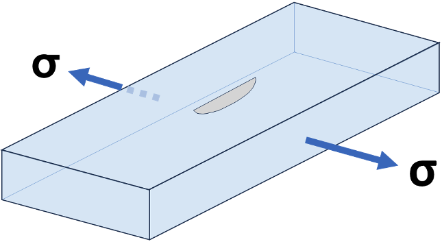
Figure 1. Idealized 2:1 Elliptical Surface Flaw.
Fracture mechanics calculations are typically based on an elliptically shaped flaw, normal to the surface and perpendicular to the stress field (e.g., Figure 1). Unfortunately, actual flaws are often not of such convenient geometry. When nondestructive examination (NDE) identifies these not-quite-ideal flaws, some interpretation is needed to allow us to apply the available fracture mechanics formulas. This is where the categorization rules come into play. Usually, the rules are common-sense idealizations of the flaw size, shape, and orientation that result in a conservative geometry that can be analyzed by traditional closed-form fracture mechanics formulas available in the Level 2 procedures of API 579, Part 9. These categorization rules are found in the “Data Requirements” section, specifically Section 9.3.6.
I’ll step through the various types of categorizations that must be addressed.
Flaw Length (§9.3.6.2)
When the flaw is not perpendicular to the principal stress plane, some adjustment is required. As you might expect, the flaw can be projected into components in two planes (see Figure 2). As you might not expect, this projected length is NOT simply a function of...


Comments and Discussion
Add a Comment
Please log in or register to participate in comments and discussions.