Inspection of heat exchanger tubing is widely used in the oil & gas, petrochemical, power generation, and nuclear industries. During heat exchanger inspections in the oil & gas industry, there are recurring issues of tube failures. A heat exchanger acts as the lifeline of the oil & gas process that transfers heat from one medium to another. Performing baseline inspections on new heat exchanger tubes can ensure the integrity of the tubes prior to installation and service, and by establishing a baseline of the equipment, operators can initiate a corrosion monitoring program.
Baseline inspections of heat exchangers are becoming more common due to issues found during the manufacturing process. Many refineries and chemical plants have incorporated an inspection program through risk-based inspection (RBI) using API RP 581, which provides guidelines to follow when performing inspections on heat exchanger tubes.[1]
Tubes manufactured at the mill will undergo several design changes. Some of those changes are known as electrical resistance welding (ERW), drawn over mandrel tubing (DOM), and seamless tubing (extrusion process). Some tubes manufactured at mills may also go through an inspection technique known as eddy current testing (ECT).
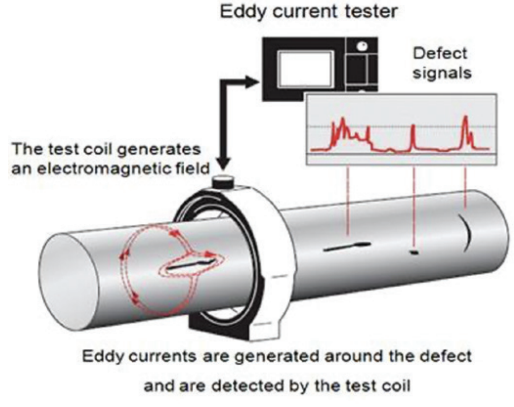
ECT is performed when the tube is inserted into the encircling coil, followed by an electromagnetic field being generated in the tube. If the electromagnetic field meets a material defect, a reaction occurs in the eddy current field and that reaction is then detected by the receiver and measured on the eddy current scope. The tubes are axial guided through an encircling coil (Figure 1) to find surface imperfections, seams, and manufacturing defects. Though effective in theory, this process is often unreliable due to the fill factor (lift-off), axial speed, inside diameter (ID) detection of weld defects, anomalies, and inexperienced operators.


Comments and Discussion
There are no comments yet.
Add a Comment
Please log in or register to participate in comments and discussions.