Introduction
API 579-1/ASME FFS-1, Part 6 defines pitting as:
“localized regions of metal loss that can be characterized by a pit diameter on the order of the plate thickness or less, and a pit depth that is less than the plate thickness.”
The fitness-for-service (FFS) assessment procedures in Part 6 can be used to evaluate four types of pitting:
- Widely scattered pitting that occurs over a significant region of the component
- Local thin area (LTA) located in a region of widely scattered pitting
- Localized regions of pitting
- Pitting confined within a region of a LTA
API 510, 7.4.3 addresses widely scattered pitting by providing an FFS assessment procedure with three different conditions that if met, considers the pits to be widely scattered and may be ignored by the inspector; or if not met, then the pits should be considered as a local thin area and analyzed accordingly.
On this basis, while performing a pressure vessel inspection, an inspector may ignore widely scattered pits if all of the following criteria specified in API 510, 7.4.3 are met.
- The remaining thickness below the pit is greater than ½ the required thickness (½ t required). Note: This condition addresses the risk for an isolated leak due to a single, deep pit.
- The total area of the pitting that is deeper than the corrosion allowance, does not exceed 7 in2 (45 cm2) within any 8-inch (20 cm) diameter circle. Note: This condition safeguards the equipment from having a group of pits that, together, become a locally thinned area.
- The sum of the pit dimensions, for pits deeper than the corrosion allowance along any straight 8-inch (20 cm) line, does not exceed 2 inches (5 cm). Note: This condition is meant to prevent an alignment of pits into a crack-like formation that may render the vessel vulnerable to fracture.
The following CASTI Connecting-the-Code© examples demonstrate how each of the three conditions listed in API 510, 7.4.3 may be considered.
Example 1: Evaluation of Pitting Using Remaining Thickness
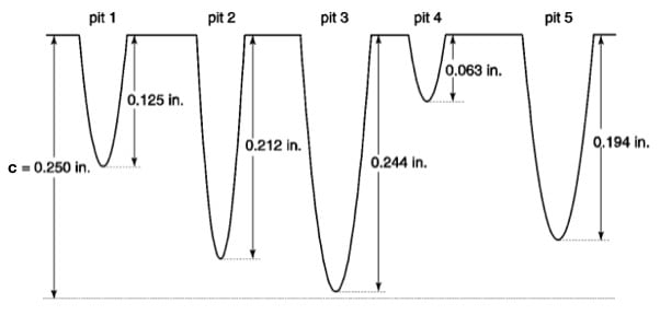
When evaluating widely scattered pits as part of an FFS analysis of corroded regions in a pressure vessel that has an inside diameter of 6 feet, required thickness of 1.5 inches, and a corrosion allowance (c) of 0.250 inches, given the following data, may these pits be ignored?
| Pit 1: 0.125 inches deep | Pit 2: 0.212 inches deep | Pit 3: 0.244 inches deep |
| Pit 4: 0.063 inches deep | Pit 5: 0.194 inches deep |
From API 510, 7.4.3, widely scattered pits must meet the following criteria to be ignored:
- Remaining thickness below pits is greater than ½ of the required thickness.
- The total area of pits deeper than the corrosion allowance does not exceed 7 in.2 within any 8-inch diameter circle.
- The sum of pit dimensions deeper than the corrosion allowance in any straight 8-inch line does not exceed 2 inches.
Reviewing the Three Conditions:
- Since none of the pits are below the corrosion allowance, then the pits are also not below ½ of the required thickness and likewise the 7.4.3 a) requirement is met.
- Since none of the pits are below the corrosion allowance, then the 7.4.3 b) requirement is met.
- Since none of the pits are below the corrosion allowance, then the 7.4.3 c) requirement is met.
Conclusion: Since the widely scattered pits meet all of the 7.4.3 requirements, then the pits may be ignored.
Example 2: Evaluation of Pitting Using Pit Area
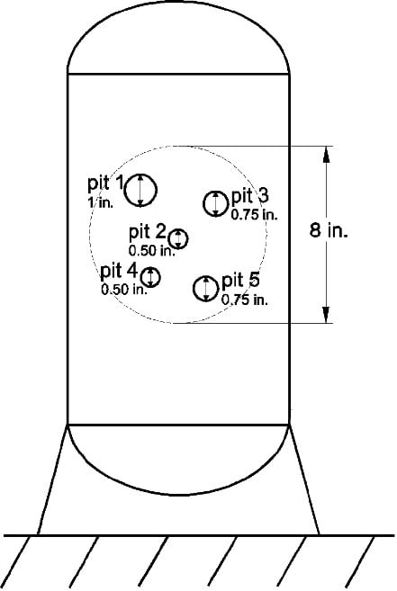
When evaluating widely scattered pits as part of an API 510 FFS analysis of corroded regions in a pressure vessel, the following data was recorded during the current inspection: inside diameter of 4 feet, required thickness of 1 inch, corrosion allowance of 0.125 inches, all pits are contained in an 8-inch diameter circle, no pit is greater than ½ the required thickness, but all pit depths exceed 0.125 inches, and the sum of the pit dimensions is satisfactory. What is the total area of the pitting with the following data and may these pits be ignored?
| Pit 1: 1-inch diameter | Pit 2: ½-inch diameter | Pit 3: ¾-inch diameter |
| Pit 4: ½-inch diameter | Pit 5: ¾-inch diameter |
Formula
API 579-1/ASME FFS-1, Part 6, characterizes pitting as having a pit diameter, and so the area of a pit can be calculated using the following formulas:
A = Area of a circle
r = Radius of a circle
d= Diameter of a circle
Read Related Articles
A (pit) = πr2
where, r = 
Required Variables from 7.4.3(b):
d (pit 1) = 1 inch
d (pit 2) = 0.5 inches
d (pit 3) = 0.75 inches
d (pit 4) = 0.5 inches
d (pit 5) = 0.75 inches
A (pit 1) = π = 0.785 in.2
A (pit 2) = π = 0.196 in.2
A (pit 3) = π = 0.442 in.2
A (pit 4) = π = 0.196 in.2
A (pit 5) = π = 0.442 in.2
Total Area = A (pit 1) + A (pit 2) + A (pit 3) + A (pit 4) + A (pit 5)
= 0.785 in.2 + 0.196 in.2 + 0.442 in.2 + 0.196 in.2 + 0.442 in.2
= 2.06 in.2
Conclusion: Since the total pitting area of 2.06 in.2 is ≤ 7 in.2, then the pits may be ignored.
Example 3: Evaluation of Pitting Using Pit Depth
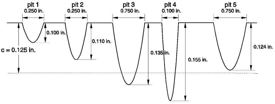
When evaluating widely scattered pits as part of an FFS analysis of corroded regions in a pressure vessel the following data was recorded during the current inspection: inside diameter of 4 feet, required thickness of 1 inch, corrosion allowance of 0.125 inches, no pit is greater than ½ the required thickness and the total area of pitting is satisfactory. What is the sum of the pit dimensions that is deeper than the corrosion allowance (c) with the following data taken along a straight 8-inch line and may these pits be ignored?
| Pit 1: 0.250 inches diameter, 0.100 inches deep | Pit 2: 0.250 inches diameter, 0.110 inches deep | Pit 3: 0.750 inches diameter, 0.135 inches deep |
| Pit 4: 0.100 inches diameter, 0.155 inches deep | Pit 5: 0.750 inches diameter, 0.124 inches deep |
Formula
From API 510, 7.4.3(c):
Depth Below c = Pit Depth – c
Required Variables:
Pit 1 depth = 0.100 inches
Pit 2 depth = 0.110 inches
Pit 3 depth = 0.135 inches
Pit 4 depth = 0.155 inches
Pit 5 depth = 0.124 inches
c = 0.125 inches
Only pits 3 and 4 are deeper than the corrosion allowance:
d (pit 3) = 0.750 inches
d (pit 4) = 0.100 inches
Therefore:
sum of pit dimensions = d (pit 3) + d (pit 4)
= 0.750 inches + 0.100 inches
= 0.850 inches
Conclusion: Since the sum of the pit dimensions deeper than the corrosion allowance in any straight 8 -inch line is less than 2 inches, then the pits may be ignored.
Alternative Evaluation Methods for Thinning Below the Required Thickness
For alternative evaluation methods of thinning below the required thickness in pressure vessels and their components, API 510, 7.4.4 permits the use of design by analysis methods of either ASME Section VIII, Division 2, Appendix 4, or API 579-1/ASME FFS-1 Appendix B-1. These methods can also evaluate blend ground areas of defect removal when such removal reduces the wall thickness below the corrosion allowance.
There is one additional rule when using ASME Section VIII, Division 2, Appendix 4 as an alternative method for evaluating thinned areas. This rule is based on substituting the Sm value of Division 2 with the stress value used in the original pressure vessel design. If the:
- design stress is ≤ ⅔-specified minimum yield strength (SMYS) at temperature, then the stress value used in the original pressure vessel design may be used; or
- original design stress is > ⅔-specified minimum yield strength at temperature, then ⅔-specified minimum yield strength shall be substituted for Sm.
In either case, an engineer shall perform this analysis when used.
References
- American Petroleum Institute. Fitness-For-Service: API 579-1/ASME FFS-1. 2nd ed., 2007.
This article was written in furtherance of a joint endeavor undertaken by CASTI and ASTM International to promote technical training and bring subject matter expertise to people around the world. This partnership enables CASTI and ASTM to deliver cost-effective education to anyone with an internet connection.


Comments and Discussion
Add a Comment
Please log in or register to participate in comments and discussions.