Thanks to constantly improving technology developments, inspection of atmospheric storage tanks has yielded better data which, when used as input, improves the accuracy of advanced assessment techniques. Coupling the improved inspection data with an advanced engineering assessment often means that tank operators are able to postpone repairs until the next shutdown, eliminate the need for repairs or be exempt from hydrostatic testing.
The emergence of fitness-for-service standards has advanced the state of the art in tank integrity assessment. The application of API 579/ASME FFS-1 Fitness-for-Service rules means that common damage mechanisms such as corrosion, shell bulging, cracking and edge settlement no longer automatically require costly repairs. The fitness-for-service methods and advanced engineering analysis make the most of the standard data collected during required inspections and help define new inspection requirements when additional inspection becomes necessary to "fine-tune" the assessment.
Several examples of advanced engineering analyses are presented here. Each highlights the use of valuable data collected during standard out-of-service inspections as well as new inspection techniques for in-service and out-of-service inspections. The case histories demonstrate how the engineering analysis can often be used to avoid costly repairs and downtime.
Hydrostatic Test Exemption
The purpose of a hydrostatic test exemption analysis is to establish that the repaired tank is fit for continued service without the need for a hydrostatic test by application of detailed stress analysis and fracture mechanics technology per API 653. Repairs requiring hydrostatic testing include floor replacement, shell repairs for removing nozzles and new nozzle installations. The application of advanced fitness-for-service methodology allows for many tanks to be exempt from hydro testing.
A hydrostatic test exemption analysis has many benefits. It eliminates the cost and time of the hydrostatic test itself as well as costs of treatment and disposal of the water used for the test. The exemption is particularly well suited for tanks repaired during the winter, when cold temperatures make hydrostatic testing extremely difficult. Furthermore, eliminating a hydrostatic test allows an operator to return the tank to service earlier.
Much of the input data required to complete the hydrostatic test exemption is standard data collected during a thorough API 653 internal inspection. Minimum measurements of each shell course thickness, general tank dimensions, materials of construction, service product specific gravity, etc. are all pieces of information available in an internal inspection report which are used for the fitness-for-service assessment.
To determine if the repaired tank is fit for service without the need for a hydrostatic test, a fracture mechanics analysis is performed to establish the critical sizes of surface connected defects located in the repaired regions. The tank is considered safe if all flaws are reliably detected and eliminated before the flaws grow to critical size. Otherwise, flaws may grow to critical size and cause catastrophic failure prior to being detectable.
In order to perform a fracture mechanics analysis (FMA), the stresses imposed on the region of interest must be established. A simple finite element analysis (FEA) model can be used to simulate the storage tank hydrostatic test when the tank is filled with water (which has a specific gravity that may exceed that of the contents during operation). An example of an FEA model is shown in Figure 1. Shell thickness obtained from inspection data can be incorporated in the finite element model.

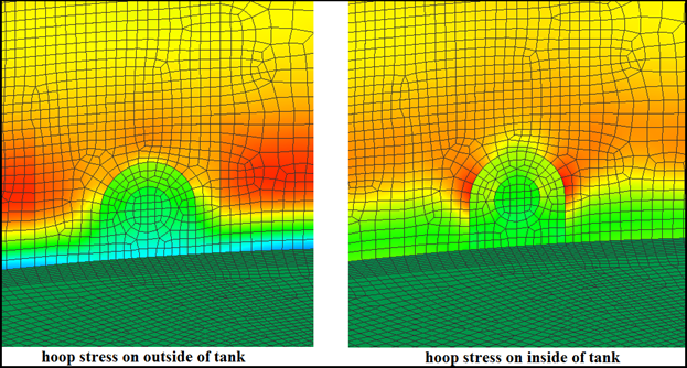
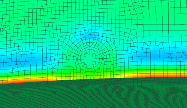
Stress results from the FEA are examined for two stress directions: the hoop stress on the outside surface of the tank and the bending stress at the shell to floor fillet weld on the inside of the tank. Figure 2 shows an example of hoop stress results on the outside surface of the tank and the inside surface of the tank at the same location. The locations of maximum hoop stress typically occur at the edge of an insert plate or reinforcing pad in the first shell course. Figure 3 illustrates another example, showing that the bending stress at the bottom fillet weld connecting the tank wall to the tank bottom is of concern.
The material fracture toughness is required to perform an accurate fracture mechanics analysis. When repairs to the tank do not yield any samples for material testing, the material toughness is determined from lower bound estimates described in API 579/ASME FFS-1. Lower bound estimates are designed to be conservative.
Once the applied stress and material toughness are established, critical defect sizes for regions of interest can be calculated. For this analysis, Quest Integrity Group's commercial software Signal Fitness-for-Service is used. This is a Windows-based program that implements methodologies described in the British Standards BS-7910 as well as API 579/ASME FFS-1 Part 9 Level 3. Signal Fitness-for-Service is used to establish critical defect sizes. For this work, the flaw is assumed to be a semi-elliptical surface crack in a flat plate with a surface length, "2c" and a depth, "a". For a semi-elliptical flaw, there is no unique critical flaw size (2c and a). Instead combinations of 2c and a resulting in a critical flaw are plotted as a line on a graph of surface crack length versus crack depth. It is important to select inspection methods that are sensitive enough to detect flaws/defects prior to reaching maximum tolerable sizes.


Comments and Discussion
There are no comments yet.
Add a Comment
Please log in or register to participate in comments and discussions.