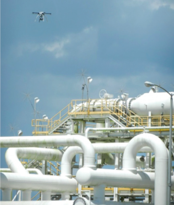
Infrared (IR) technology is widely used in the oil and gas industry as an inspection tool for condition monitoring and predictive maintenance. It is advantageous over traditional visual inspection and other tools because infrared technology does not have to be in contact with the equipment being monitored.
IR thermography is a form of nondestructive testing that measures temperature variances of a component as heat (i.e. thermal radiation) flows through, from, or to that component. IR thermography is also generically known as IR testing, thermal testing, thermal imaging, and IR thermometry.
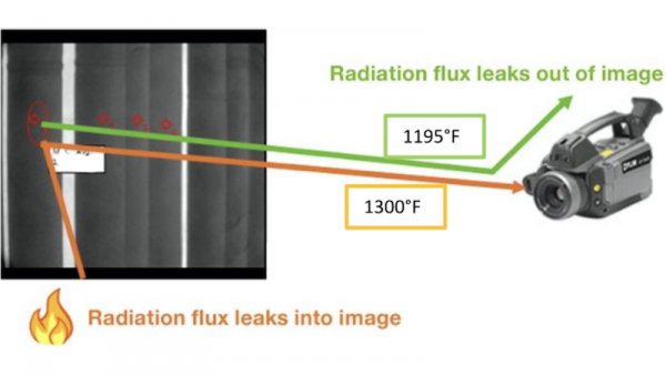
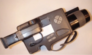
Thermal radiation is directly related to changes in temperature. In other words, as a component changes temperature, the amount of radiation emitted changes. Since this type of radiation is a form of electromagnetic waves that cannot be seen with the human eye, components have to be analyzed using infrared cameras. Infrared cameras are able to detect and display emitted, reflected, and transmitted infrared energy from an component. The thermal image can then be analyzed to obtain a temperature reading for the component.
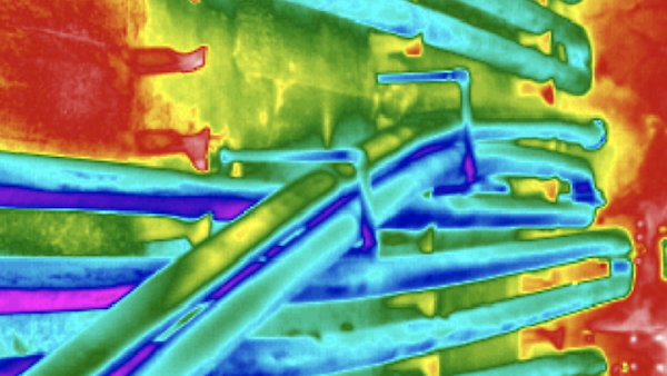
The purpose of mapping temperature levels and variances of a component is to detect any hot spots where equipment may weaken or fail. IR thermography is also capable of detecting corrosion damage, delaminations, voids, inclusions, and other flaws that affect heat transfer. However, in order to detect these anomalies, there must be sufficient temperature difference between the component and its surroundings.
Fundamental IR Thermography Concepts
Emissivity refers to a material’s ability to emit infrared energy. Emissivity is expressed as a value between 0 and 1 where 0 describes a perfect mirror surface and 1 describes a blackbody. For example, a material with an emissivity value of 0.95 absorbs and emits 95% of infrared radiation and reflects 5% of the surrounding radiation.
Reflectance refers to the amount of light reflected from the surface of a material.
Transmittance is a material’s ability to transmit thermal energy (i.e. heat) from a component being tested to an infrared camera. For example, plastics are transmissive while metals are opaque and are not transmissive.
Heat vs Temperature
These terms are commonly used interchangeably. Although they are related, they have very distinct meanings.
- Heat is a measure of the total energy of molecular motion of an object and is dependant on the size of the object. Heat also describes how thermal energy transfers from one object to another or its surroundings.
- Temperature refers to an object’s average energy of molecular motion and, unlike heat, can be measured directly. Temperature does not depend on the size of the object.
Heat Transfer describes the phenomenon of thermal energy transferring from a hotter temperature region to a colder temperature region.
Heat Transfer Mechanisms — Heat can transfer in three ways:
- Conduction is the transfer of heat between two solids.
- Convection is the transfer of heat through liquids and gases.
- Radiation is the transfer of heat through electromagnetic waves.
Thermography Considerations
Component Factors
In terms of equipment being tested, operators and inspectors should have working knowledge about the:
- Equipment and process
- Material type (e.g. steel, stainless steel, etc.)
- Material properties (e.g. thermal diffusivity)
- Thickness and geometry of the component
- Emissivity of the material
Anomaly Factors
If infrared technology is being used to detect flaws, knowledge about the size, depth, and orientation of the anomaly must be known.
IR Camera Factors
Several instrumental factors to consider when performing IR testing include:
- The distance between the component and the IR camera
- Spatial resolution output (i.e. clarity of component)
- Thermal resolution output (i.e. clarity of temperature differences)
- Thermal range (i.e., ability to detect temperatures of the component being tested)
IR Testing Techniques
Several IR testing techniques exist and the decision on whether and which to use depends on the the considerations listed above.
Passive Thermography involves testing the component during or after operation. The primary advantages of this method are that it does not require an external energy source and equipment doesn’t have to be taken out of service.
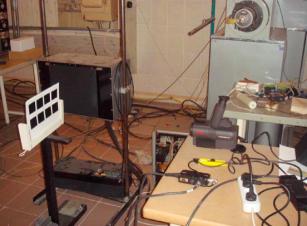
Active Thermography requires an external energy source that produces thermal variances in the component. The component is monitored until it has reached thermal equilibrium. This technique is useful for determining how heat flows through, from, or to a component before it is placed in service. This method is also used to locate anomalies in equipment during service.
Flash Thermography measures the changes of surface temperature after a pulse of light energy is introduced to the component. This technique is used to locate voids, inclusions, and other deflects that obstruct heat flow into the component.
Vibrothermography is a technique that utilizes acoustic waves to find cracks in a material. The acoustic energy causes friction between the two sheared surfaces of a crack, which results in the production of heat. The frictional heat is then detected using an infrared camera.
Lock-in Thermography requires that an external source of energy (e.g. light, sound, etc.) be periodically applied to the surface of a component in order to reveal a subsurface anomaly. The depth, size, and orientation of the anomaly, as well as the properties of the material, must be known in order for the method to be highly accurate. This technique is much slower than flash thermography, however, it is capable of penetrating thicker-walled components.
Industry Applications
IR thermography is utilized in many industries and applications. In the oil and gas and chemical processing industries, for example, thermography can be used to detect piping insulation issues, fluid levels, or identify trouble spots where rotating equipment is experiencing too much friction. Furthermore, IR testing is commonly used to locate hot spots and anomalies such as voids and inclusions. The benefits of IR testing include extended equipment life, decreased unscheduled shutdowns, reduced risk of equipment failure, and increased performance.
Related Topics
- Acoustic Emission Testing (AET)
- Advanced Ultrasonic Backscatter Technique (AUBT)
- Eddy Current Testing (ECT)
- Electro Magnetic Acoustic Transducers (EMAT)
- Guided Wave Ultrasonics (GWUT)
- Liquid Penetrant Examination (LPE)
- Magnetic Flux Leakage (MFL)
- Magnetic Particle Testing (MPT)
- Meandering Winding Magnetometer Array (MWMA)
- Pulsed Eddy Current (PEC)
- Radiography
- Remote Field Eddy Current (RFEC)
- Ultrasonic Testing (UT)
Relevant Links
Topic Tools
Share this Topic


Contribute to Definition
We welcome updates to this Integripedia definition from the Inspectioneering community. Click the link below to submit any recommended changes for Inspectioneering's team of editors to review.
Contribute to Definition