What is the “Remaining Strength Factor”?
In six Parts of the 2021 edition of API 579-1/ASME FFS-1, “Fitness-for-Service” (API 579), the Remaining Strength Factor or “RSF” is used as the acceptance criteria for a fitness-for-service assessment [1]. The remaining strength factor is defined in API 579, Eq. 2.1 as:
…where:
LDC = Limit or plastic collapse load of the damaged component (i.e., the component with a flaw, such as a thin area or dent)
LUC = Limit or plastic collapse load of the undamaged component
For example, if you were to perform calculations (or a finite element model) indicating that an undamaged cylinder would fail at 400 psi, and the same cylinder with a particular local thin area would fail at 300 psi, the RSF = 300/400 = 0.75.
The Parts of API 579 that use the RSF as their acceptance criteria include:
- Parts 4, 5, 6, General & Local Metal Loss and Pitting
- Part 7, Hydrogen Induced Cracking
- Part 8, Weld Misalignment & Shell Distortions
- Part 12, Dents & Gouges
The other Parts use a range of methods specific to their own damage mechanisms. Specifically:
- Part 3, Brittle Fracture – “Exemption Curves” or fracture mechanics criteria
- Part 9, Crack-Like Flaws – Failure assessment diagram (FAD)
- Part 10, Creep – Creep Damage Models
- Part 11, Fire Damage – Various
- Part 13, Laminations – Rule-based
- Part 14, Fatigue – Fatigue curves
First Appearance of the RSF
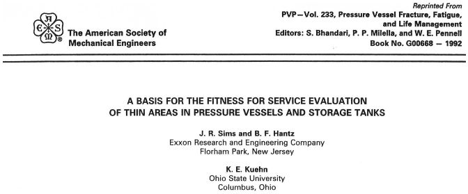
The earliest appearance of the RSF (in pressurized components) that I’ve found is in a 1992 paper by Sims, Hantz, and Kuehne (Figure 1). I remember this paper well because I was in the audience for its presentation at the 1992 PVP conference and I have a copy in my personal files [2].

Other papers by the same authors were published in 1993 and 1994. These 1993 and 1994 papers are referenced in API 579, para. 2F.2, regarding burst testing used in establishment of the RSFa = 0.9 rule [3,4].


Comments and Discussion
Add a Comment
Please log in or register to participate in comments and discussions.