| This article is part one of a 2-part series. |
| Part 1| Part 2 (Coming Soon) |
Editor’s Note: This complete assessment will be presented in two articles. This article (part one) details the overall methodology along with the qualitative, quantitative, and visual assessments which will lay the foundation for the specialized predictive techniques. The specialized predictive techniques will be presented in part two to be published in the January/February 2023 issue.
Introduction
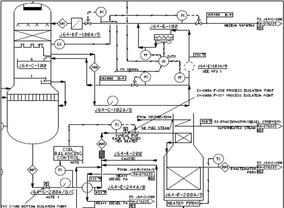
The gas condensate splitter plant processes up to 200 MBOD to produce high-quality naphtha and distillates, as shown in the schematic in Figure 1. To accomplish this, the plant uses condensate fractionation, naphtha stabilization, and support processes. The condensate fractionation process includes preheating, desalting, pre-flash preheating, pre-flashing, and fractionation. After preheating, the desalted/preheated condensate flows to the pre-flash column. Inside the column, the vapor and the desalted/preheated gas condensate flash and separate into streams, of which the light naphtha vapor forms the overhead stream flowing to stabilization. The debottlenecking study for higher production rates from 200 MBOD to 225 MBOD and 250 MBOD had identified that this pre-flash column overhead piping system could be susceptible to vibrations due to an increase in flow rates.
Problem Statement
An increased flow rate resulting from a higher required throughput was causing higher flow velocities with a correspondingly greater level of turbulent energy in the process. At first, this was suspected to be the primary concern for the vibration behavior observed and recorded on this pre-flash column overhead piping system. It was noticed during a short trial operational run of the gas condensate splitter plant. Hence, a comprehensive understanding of causes for excitation of vibration in piping was required, if an effective mitigation strategy was to be established, and moreover, the recommended field changes would not in any way introduce new piping stress and flexibility issues to the already existing vibration at higher flow rates. A detailed, structured approach based on a proactive troubleshooting technique outlined by Energy Institute’s article, “Guidelines for the avoidance of vibration induced fatigue failure in process pipework” (henceforth referred to as EIG) was followed [2].
Assessment Methodology
Since an existing plant was going to be subjected to a process change in the future 250 MBOD scenario, this approach was considered to be a proactive strategy, wherein the EIG Flowchart 3.3, as shown in Figure 2, was employed for assessing the anticipated vibrations issues with the pre-flash column overhead’s piping vibration.
Design phase: This is the period of gas condensate splitter plant operations during 200 MBD throughput and will entail completing the TM-01, TM-02, TM-03, TM-04 & TM-09 modules of EIG as detailed in the Qualitative Assessment (TM-01) and Qualitative Assessment Small Bore Connections (SBC), likelihood of failure (LOF) (TM-03) section of this article.


Comments and Discussion
Add a Comment
Please log in or register to participate in comments and discussions.