Introduction
The corrosion-related Parts of the API 579-1/ASME FFS-1, Fitness-for-Service (API 579) standard are certainly the most frequently used. This is because corrosion is an enormous and pervasive damage mechanism that affects countless aspects of industry. You’ve probably heard of the much-quoted NACE study which concludes that the “direct cost” of corrosion in 1998 was $276 billion, or 3.1% of the US gross domestic product (GDP). A recent extrapolation by G2MT Labs, accounting for the inflation-adjusted, direct-plus-indirect cost, put the total 2016 cost at $1.1 trillion; over 6% of the GDP. Suffice it to say that corrosion assessment deserves some attention.
A cornerstone of the Level 1 and Level 2 metal loss assessment methods in API 579 is the concept of measuring thickness on a grid and constructing a “critical thickness profile.” These concepts are fundamental to Level 1 & 2 assessments in both Parts 4 and 5 (general and local metal loss).
The Grid
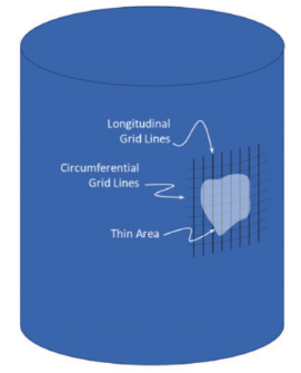
Most fundamentally, the inspection grid is just a regular series of (typically parallel) longitudinal and circumferential lines to help organize evenly spaced thickness measurements.

Figure 1 shows a typical inspection grid encompassing a thin area on a cylindrical shell. In setting up this grid, there are several points to consider.
Grid Spacing
The grid spacing should be adequate to capture the variation in the thickness. Figure 2 shows an example of the effect of grid spacing. In Figure 2(a), the spacing is too large to capture the highs and lows of the contour. In Figure 2(b), the tighter spacing captures an adequate representation. That said, it is not necessary to have spacing so refined as to ensure that all maximums and minimums are represented. This is essentially a statistical sample that requires only a good representation of the contour.


Comments and Discussion
Add a Comment
Please log in or register to participate in comments and discussions.