Introduction
For the past 4-5 decades, oil refiners and petrochemical plants have used thickness readings in their facilities. Since the PSM (Process Safety Management [1]) Regulations in 1993, the use of manual ultrasonic thickness (UT) instruments to collect data on remaining wall thickness of steel piping, tanks, and pressure vessels has greatly increased. The thickness values are plotted over time to establish the metal-loss rates, due to corrosion and/or erosion, and predict the asset’s safe remaining life. Some sites may take hundreds of thousands of manual UT readings per year.
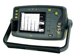
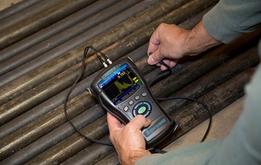
Portable devices such as analog UT flaw detectors (Figure 1) and digital thickness gages (Figure 2) have evolved significantly over this time frame. All modern devices employ the same basic measurement principle of “clocking” the round-trip transit time, in microseconds, and, by knowing the acoustic velocity of the test material, converting that short time interval into thickness using the following formula:
T= t / 2 * V where T = thickness, t = time, V= acoustic velocity
Example: 0.250” Thickness = 2.2 microseconds / 2 x 0.2266 in / µsec. (6.35 mm and 5.7 mm/µsec).
With the advent of microprocessor-based technologies in the mid-1980’s, small, lightweight, low-cost, portable digital instruments of many types became available. Improved software programs also became integral to these instruments yielding higher resolution, RF signal display, better accuracy, temperature correction, ease of use, auto-calibrating with onboard data-logging able to store the digital data including the RF waveform, and geo-location from each thickness reading.
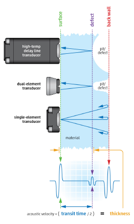
Transducer technology also advanced steadily over the past few decades to include single-element, dual-element, and delay-line probes (Figure 3) with improved temperature stability, wider thickness ranges, better durability and improved ergonomics to minimize technician fatigue. One of the latest technological advancements uses 128-element phased-array UT transducers and systems to enhance area coverage, probability of detection (POD) and create real-time 2D or 3D images of remaining wall-thickness.
Advanced Measurement Technologies
All digital ultrasonic thickness gaging capabilities are based on making very accurate and consistent round trip transit-time measurements of the high-frequency ultrasonic pulse in the test part. Instrument electronics and software must be able to calculate or identify predictable time locations of “zero thickness” and the reflected back-wall signal, as represented by its RF waveform, to achieve the wall-thickness measurement resolution necessary for corrosion engineering (i.e., to calculate a credible corrosion rate).
Consistent reference locations on the digitized RF waveform are required to...


Comments and Discussion
Add a Comment
Please log in or register to participate in comments and discussions.