Abstract
Refinery structures require frequent inspection, maintenance to maintain structural health, and safe work practices; however, accessing structures is getting harder and harder due to their enormous height and size. In order to deal with this problem, many researchers have developed several robots for wall crawling, yet there is much progress beyond this that is needed. One of the primary reasons that existing wall crawling robots haven’t been used more widely in the field are risks associated with accidental fall of the equipment due to operational failure from the harsh environment like strong winds and the unpredictability of rough surface conditions. Therefore, we tried to develop a wall-sticking aerial robot platform that can approach any area on the structure by flying to and sticking on the target. The robot is equipped with electro-magnetic hold/mount elements to “stick” the sensor probe on the ferro-magnetic surface of the structure. This paper covers installing the wall-sticking mechanism on the aerial robot.
Introduction
Unmanned Aerial Vehicles (UAV) commonly referred to as drones, have become increasingly autonomous with their flexibility and utility. UAVs started as a consumer and hobbyist phenomenon, but more recently they have grown into useful tools for remote visual inspection of industrial assets and an array of other enterprise uses. Last year alone, UAV startups saw more than $450 million in investments.[1] UAVs are a great compliment to technologies already utilized in the inspection industry today. Commercial demand for UAV inspections is growing rapidly and new applications are explored daily.
While non-contact based UAV inspection, such as visual, optical, IR, LIDAR, and Gas detectors etc., is moving quickly to a commodity business, significant efforts must still be made in aerial robotics and nondestructive testing (NDT) measurement technology to enable conventional contact NDT, such as Ultrasound testing (UT) and Eddy-Current testing (ECT).
The objective of the project discussed herein was to develop UAV inspection solutions integrating the most recent robotics technologies. More specifically, to deliver industrial aerial robots capable of performing contact NDT, such as UT and ECT, leveraging compact, wireless inspection technologies.
Throughout their life, aboveground storage tanks are exposed to considerable operational and environmental forces, and subject to corrosion and cracks at the surface and subsurface levels. Usually cranes, scaffolding, rope-access and numerous personnel are used to inspect both the storage tanks and the overall structure. Executing maintenance and inspections can be costly, time consuming, and risky for those who carry out the work. One potential solution to this could be autonomous UAVs.
Inspection robots already play an important part in the Oil & Gas industry by helping with inspection, monitoring, and surveillance of complex structures. The use of robots can help reduce human involvement (physical), increase operational efficiency, reduce cost and improve safety.
Concept of a Wall-Sticking UAV
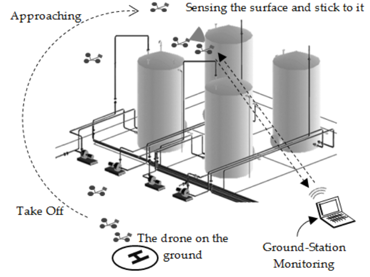
A UAV can “stick” to the wall of a structure by combining the thrust force and electromagnetic force with maximized friction between the drone wheel and the surface.[2,3] In our tests, we were able to stick an unmanned aerial vehicle to a storage tank wall by combining thrust force and electromagnetic force to press the sensor probe on the metal surface. If the friction coefficient is higher than 1, the robot can stick to the vertical surface with the thrust force toward to the wall.[4,5] We have investigated this mechanism using a simple tricopter and conducted outdoor experimental tests. Figure 1 illustrates the principle of a wall-sticking UAV.
System Description
Contact-based UAV inspection was studied to evaluate the possibility of conducting ultrasonic thickness testing at random spots on structures that can be found in the oil and gas and petrochemical industries, such as storage tanks. The project is for determining the feasibility of attaching the ultrasonic sensor probe to an open-source robotics vehicle (See Figure 1).
While designing the system, the primary features and functionality desired were ease of use, modularization for fast deployment of sensors, real-time data display, and importantly, compliance with safety codes and regulations for hazardous environments.
Read Related Articles
The UAV utilized in these tests was capable of vertical take-off and landing (VTOL). It was selected based on the following set of criteria:
- Cost and availability
- Spare-parts and ease of reparability
- Open-source hardware and software
Frame Design
The UAV is tri-copter or (yaw) and the goal is that the yaw functions differently. The rear motor pivots giving yaw more like a helicopter whereas a Quad-copter uses differential torque to achieve yaw. Differential torque is weaker and slower than yaw. The Quad works assuming that the system is basically in balance and only a slight change in torque will yield yaw. In contrast, pivoting the rear motor will yield more powerful true and direct yaw control (see Figure 2).
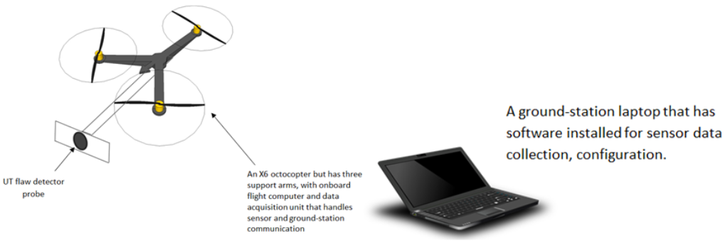
The main materials of the UAV frame are carbon fiber plates and pipes. The selection of motors was based on the frame size, propeller size, battery capacity, and motor drive. Figure 3 shows the UAV general system block diagram.
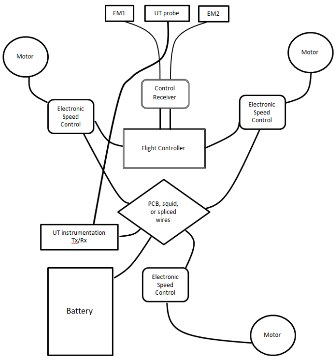
Interchangeable sensor modules were attached to the platform. Sensor data was relayed through the flight computer via a wireless link to the ground station app. The ground station application software displays the sensor data in real time. The UAV platform consisted of a Y Copter access panel (S), tri copter battery tray, landing gear plates, Y Copter frame, Motor mount for pivoting motor, M3 and M4 lock nut retainer plates, servo mount, stationary motor mounts, servo mount carbon tab (ENV), GPS sensor, 16,000 mAH battery, receiver/transmitter for RC, ESC's for motors, and a Pixhawk control module. EM1 and EM2 are electromagnetic probes.
The assembly supports an expandable interface for attaching custom sensors to the UAV, overcoming the limitation of some single-purpose platforms which are costly to convert for other tasks. Since the sensor system is modularized, sensors could be exchanged rapidly. The hardware platform easily accommodates sensors. It is possible to use an established open-source infrastructure to collect sensor probe data from the UAV in real time. The UAV need not be visible to the operator; however some degree of line-of-sight is required to ensure the signal is not dropped and real-time data lost. The sensor gauge module with its transceiver unit is fitted inside the canopy and can be fitted to the bracket in various ways. This will not interfere with the structural integrity of the drone as long as the module is kept within certain physical limits.
Wall-Sticking
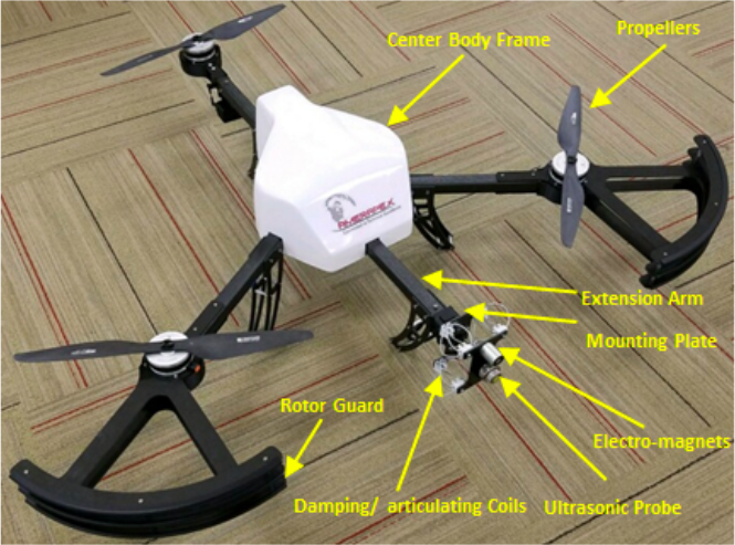
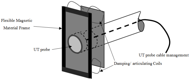
The UAV has a capacity of hovering like most common drones, and is manually controlled by an operator remotely. It houses a fixed extension arm that extends far from the neighboring blades with a mounting plate that contains a compact and lightweight articulating flexible coil (see Figure 4). During data acquisition, a UAV may, based on the quality of the steering and/or the effect of a cross winds, undergo rotational movements about its pitch axis such as vertical movement (up or down) and/or side movement (right or left).
Such sudden, abrupt events may cause the detachment or removal of the UAV’s sensor probe from the surface being interrogated and prevent it from taking the inspection readings. An articulating joint or (coil) assists by absorbing the impact when the UAV flies directly to the target surface and lands on the probe side (front side of the UAV). By combining the thrust generated by the UAV and the electromagnetic units that surround the probe, proper pressurization and contact distribution of the sensor probe against the surface is achieved.
Front rotor guards made from carbon fiber were installed on this particular unit to protect them from contact with the wall. The ultrasonic probe takes a measurement when applied against a surface. When the UAV attaches to target wall, it is held stationary for a few seconds (2 to 3 seconds) to take UT measurements. This allows measuring the thickness of the metal surface under examination per ASNT “Ultrasonic Testing Standards and Practices.” The ultrasonic probe induces a 00 compression wave ultrasonic signal that travels through the surface and subsurface, and the reflected signal from the back surface is detected by the probe and is converted to a digital thickness reading.
The test was initially conducted with the sensor onboard without any type of magnet. Later, to keep it from moving on the surface, we added a small permanent magnet. The controls eventually had an issue because of the fixed heading setting in the control logic. This caused the rudder/yaw to behave incorrectly more than a few times. To make this work long-term, a decision was made to modify the flight control code by putting it in a “rate” gyro mode when pushing against the wall. This prevented over control and allowed the drone to steadily, yet with some motion flexibility, push against the wall establishing a good couple for the measurement and without any significant issue.
We tested with a light, flexible permanent magnet (shown in Figure 5). Its adhesive force is 32 lbs., has a width of 1”, and it weighs 3.3 oz.
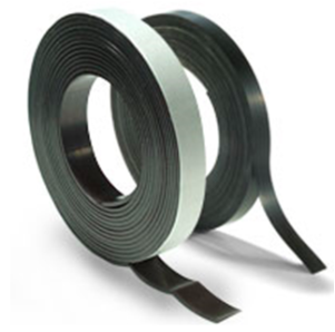
The flexible magnetic material was wrapped around the mount frame of the probe, as shown in Figure 6. However, the test flight showed we can push the UAV against the wall and it stays relatively stable without the permanent magnet. The permanent magnet did not show any significant help to sticking the probe on the wall, as we determined that the magnet’s surface contact area is not sufficient enough to generate the needed traction force. The effective force would require a permanent magnet, that would be too bulky and heavy, hence, not feasible for this purpose.
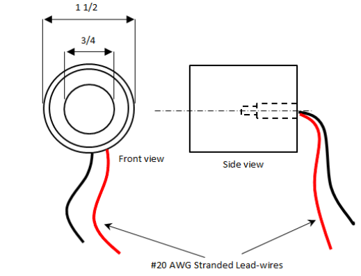
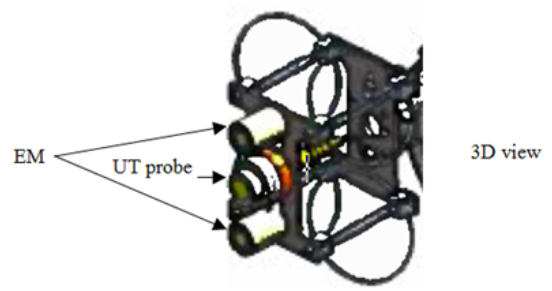
To achieve the sticking force and stationary level needed to take a reliable reading, two electro-magnets (EM) are suggested. EM combines the advantages of electro and permanent magnets. Each EM used is a round design that provides adhesive forces of up to 120 lbs. They are made of a zinc-plated case, 1.5" diameter × 1.5" long - weight 10 oz. The electrical specifications are: #20 AWG lead wires × 24" long outside of the magnet, 12 VDC, 4.0 watts, and 100% duty cycle standards. The device creates a very strong magnetic contact with a ferrous target, and it supports UAV, RC remote control. In this particular unit, the ultrasonic probe and both EMs are housed in one aluminum plate as shown in Figure 7a and 7b.
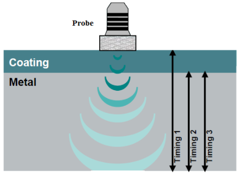
The ultrasonic thickness gauge used is a commercial off-the-shelf unit that is designed for common thickness gauging applications with the added benefit of being able to store measurements within the gauge. All ultrasonic thickness gauges should be calibrated to the acoustic velocity of the material being measured. Coatings have different velocities of sound than metal. It is important that coating thicknesses or their effects are not included in the measurement of the metal substrate. The use of being able to perform a UT multiple echo measurement makes it possible to identify the coating and eliminate it from the measurement. The probe used was a 2.25 MHz probe that works well on heavily-corroded metal. Its resolution and accuracy are 0.1 mm (~0.005 inch) and ± 0.1 mm (~0.005 inch), respectively. A transmitted ultrasound pulse travels through both the coating and the metal and reflects from the back wall. The returned echo then reverberates within the metal, with only a small portion of the echo travelling back through the coating each time. The timing between the small echoes gives the timing of the echoes within the metal, which relate to the metal thickness. The gauge will interpret the echoes automatically and calculate the thickness. The measuring range of a 2.25 MHz probe goes down to 3 mm (0.120”), which is perfectly acceptable in most applications. This technique is referred to as the automatic measurement verification system (AMVS) (see Figure 8).
Lithium-Ion batteries were used to power the system due to their light weight, large capacity, high discharge rate, and good energy storage to weight ratio. The readings picked up by the sensor module were relayed directly to a mobile ground station using the telemetry modules; on the drone, the radio link module was connected directly to the flight computer.
A dry couplant (Elastomer) designed specifically for ultrasonic inspection applications was attached to the probe for contact inspection. Unlike other dry couplants normally used as an integral part of ultrasonic probes, this elastomer can be applied independently of the probe. Acoustic impedance of the material is nearly the same as water and its attenuation coefficient is lower than all other documented elastomers and many plastics. It is flexible couplant pad with extreme low (≈ zero) velocity delay lines, avoids the drawbacks of wet coupling when used on porous or refractory surfaces. It eliminates absorption by the material and avoids messy residues.
Discussion of Related Work
Other developers in the field of UAV inspection have achieved similar outcomes in terms of visual inspection, yet fell short in contact-based inspection. Various companies are capable of visual inspections that include the detection of corrosion from an aerial perspective, which can save significant time and money when compared to alternative forms of elevated inspection. However, they still rely on a combination of inspection via UAV and inspection via personnel using probes to take measurements. The UAV discussed in this article demonstrated the ability to successfully combine visual inspection and contact-based inspection.
Test and Result
The feasibility of UAV ultrasonic testing was examined by developing a tricopter-based drone and conducting outdoor experimental tests using the weak permanent magnets, as shown in Figure 6. The author initially used a simpler and smaller version of the tricopter for testing while fine-tuning the flight control codes in order to minimize damage to the main unit.
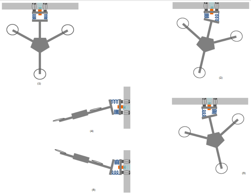
The UAV tests have shown that the drone takes off from the ground and hovers near the target area with high stability, and sticks to it using the EMs and force/pressure from the drone itself. As seen in the hovering scenarios in Figure 9, the different scenarios show how the drone would maintain contact even with the existence of movement or instability due to high wind speed or other mechanical instability. The EM is powerful enough to hold the drone, and it has flexible ring-like coils at the corners of the mounting plate that enable it to pivot left, right, up, and down, while the sensor is continually making steady contact.
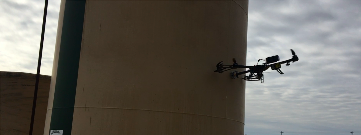
In a real-world inspection demonstration on a crude oil storage tank (nominal thickness = 0.2 inches) (as shown in Figure 10a) the UAV takes off and hovers to reach its target on the storage tank wall. When it is close to the target, the operator remotely sends the TURN ON command to the EMs. The UAV sticks to the wall, and the probe will induce the ultrasound as soon as contact is made. Thickness measurements are immediately taken and the data is displayed in real-time on the ground-station laptop (see Figure 10b). It can measure the thickness of the storage tank wall with up to ± 0.005 inch accuracy.
After receiving the data, the operator will send the TURN OFF command to the EMs. The UAV will then be free to fly to the next desired location. The author attempted 10 flight tests per battery. Each flight took no more than 20 seconds (including take off, hover to the inspection spot, stick to the surface for inspection, and send the data wirelessly to the ground). The experimental test showed a 90%+ success rate of wall-sticking without the EMs, while with the EMs it was 100%. Flight time reached up to 15–20 minutes per battery pack. During the tests, the wind speed averaged 22 mph. The process is shown in Figure 10c where the thicknesses were measured 10 times manually versus using the drone.
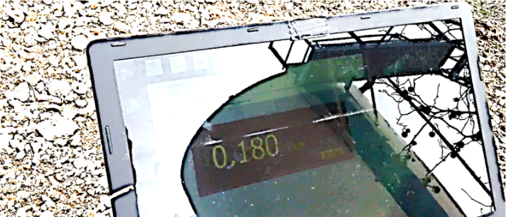
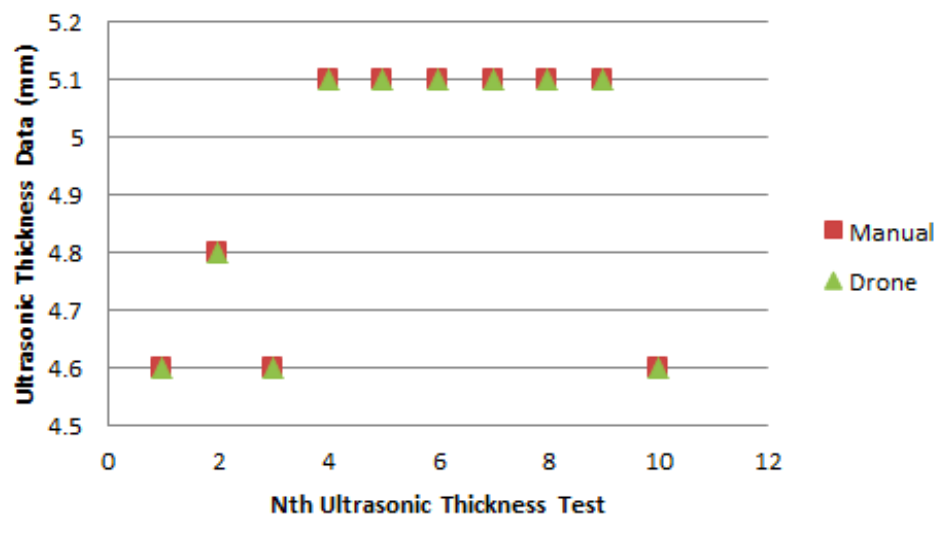
The result also showed that the collected measurement data ranged from 0.18 to 0.2 inches. Data from the UAV matched the manually-taken data 100%. Based on the author’s findings, in cases where the target structure is coated with an anti-corrosion paint layer or any sort of coating layer that impairs the EMs “sticking” effectiveness, tests could still be successfully conducted via the back pressure produced by the drone, holding the probe in place with good stability. This also applies to non-metallic and non-magnetic surfaces, such as concrete, composite, stainless steel and wooden structures, etc.
Conclusion
In this article, we have demonstrated feasibility of the wall-sticking robotic UAV. From tests conducted in the laboratory and in the field on a storage tank, it is clear that ultrasonic testing and other NDT methods can be deployed effectively on equipment at elevated heights utilizing a UAV.
Acknowledgement
The author would like to thank Remy Kalai for his assistance in the development of this article.
References
- The Inspectioneering Journal. Available online: https://inspectioneering.com/news/2016-04-18/5276/
- american-petroleum-institute-supports-new-drone-technology (accessed on 10 October 2017).
- Glez-de-Rivera, G.; Garrido, J.; Ponticelli, R. Design considerations of a small UAV platform carrying medium payloads. In Proceedings of the 2014 Conference on Design of Circuits and Integrated Circuits (DCIS), Madrid, Spain, 26–28 November 2014.
- Shin, J.U.; Kim, D.; Kim, J.H.; Myung, H. Micro-aerial vehicle type wall climbing robot mechanism for structural health monitoring. In Proceedings of the IEEE SPIE 2013 (Smart Structures and Materials + Nondestructive Evaluation and health Monitoring), San Diego, CA, USA, 10 March 2013.
- Xiao, J.; Wang, H.J. Contemporary Issues in Systems Science and Engineering; CHAPTER22: Advances in Climbing Robots; Wiley, Texas, USA-IEEE Press: 2015.
- Myeong, W.C.; Jung, K.Y.; Jung, S.W.; Jung, Y.H.; Myung, H. Development of a drone-type wall-sticking and climbing robot. In Proceedings of the 12th International Conference on Ubiquitous Robots and Ambient Intelligence (URAI 2015), Goyang, Korea, 28–30 October 2015.
- Industrial SkyWorks. Available online: http://industrialskyworks.com/oil-and-gas-drone-inspections/ (accessed on 10 December 2017).
- sUAS News, the Business of Drones. Available online: https://www.suasnews.com/2017/10/catec-develops-aerial-contact-technology-inspection-drones/ (accessed on 12 December 2017).
- Center for Advanced Aerospace Technologies (CATEC). Available online: http://www.catec.aero (accessed on 12 December 2017).
- Ellenberg, A.; Branco, L.; Krick, A.; Bartoli, I.; Kontsos, A. Use of unmanned aerial vehicle for quantitative infrastructure evaluation. J. Infrastruct. Syst. 2014, 21, 04014054.
- Sankarasrinivasan, S.; Balasubramanian, E.; Karthik, K.; Chandrasekar, U.; Gupta, R. Health monitoring of civil structures with integrated UAV and image processing system. Procedia Comput. Sci. 2015, 54, 508–515.
- Eschmann, C.; Kuo, C.M.; Kuo, C.H.; Boller, C. Unmanned aircraft systems for remote building inspection and monitoring. In Proceedings of the 6th European Workshop on Structural Health Monitoring, Dresden, Germany, 3–6 July 2012.
- Eich, M.; Vögele, T. Design and control of a lightweight magnetic climbing robot for vessel inspection. In Proceedings of the 2011 19th Mediterranean Conference on Control & Automation (MED), Corfu, Greece, 20–23 June 2011.
- Shukla, A.; Xiaoqian, H.; Karki, H. Autonomous tracking and navigation controller for an unmanned aerial vehicle based on visual data for inspection of oil and gas pipelines. In Proceedings of the 2016 16th International Conference on Control, Automation and Systems (ICCAS), Gyeongju, Korea, 16–19 October 2016.
- Lee, W.; Nam, J.; Jang, B.; Jang, G. Selective motion control of a crawling magnetic robot system for wireless self-expandable stent delivery in narrowed tubular environments. IEEE Trans. Ind. Electron. 2017, 64, 1636–1644.
- Na, W.S.; Baek, J. Impedance-based non-destructive testing method combined with unmanned aerial vehicle for structural health monitoring of civil infrastructures. Appl. Sci. 2016, 7, 15.


Comments and Discussion
Add a Comment
Please log in or register to participate in comments and discussions.