Introduction
A best in class Mechanical Integrity (MI) program is comprised of numerous components, including Risk-Based Inspection (RBI), Integrity Operating Windows (IOWs), inspection strategies, and more. Inspection strategies, including Condition Monitoring Location (CML) selection, are critical in ensuring program effectiveness, as their results drive key decisions and continuous program improvement. Effective CML coverage and placement enables owner/operators to better understand and mitigate potential risks in a cost-effective manner. It also inspires confidence in the data used to make informed decisions, which ultimately maximizes the value of an MI program.
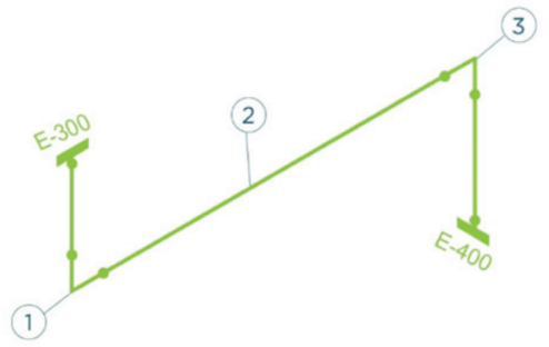
Consider a piping circuit subject to localized thinning requiring CML placement. One may choose to place spot UT CMLs on every single elbow, tee, and reducer, and one or more on each straight run, in an attempt to detect localized asset degradation (see Figure 1). Not only does this have a lower probability of confirming anticipated damage due to the selected inspection technique, but it may even cost more than a targeted inspection of likely locations by UT scan or profile RT.

Conversely, consider a circuit primarily subject to generalized thinning, with CMLs placed on each fitting. In this case, an effective inspection technique for the anticipated damage type may provide a wealth of data to be analyzed, but is it actually necessary to gather this much information? How would one know when sufficient coverage has been achieved?
As the industry continues to grow and evolve, so should the standard approach to CML selection. Traditional qualitative approaches are simple to implement, but can be highly subjective in nature—considering the availability of data, as well as advances in engineering and technology, it is possible to supplement traditional approaches with quantitative engineering and statistical methods, improving confidence that CMLs are effectively and efficiently monitoring asset degradation.
CML Optimization
The next generation of CML selection is what we refer to as CML Optimization. Put simply, this approach is a marriage between inspection and engineering—a proactive approach designed to ensure plant resources are best utilized to perform effective inspections, balancing both theory and practicality.
A common misconception when discussing the topic of CML Optimization is that its sole purpose is to reduce CMLs to the fullest extent possible. CML Optimization is not a reduction technique, although reduction may be a welcome side effect. Depending on the current level of coverage for assets experiencing general thinning, it is possible to see overall spot UT reduction across a facility, with a decrease for some assets and an increase for others. These resources can then be reallocated towards effectively monitoring other damage types through advanced NDE techniques such as UT scanning, profile RT, phased array scanning, etc.
The ultimate goal of CML Optimization is to determine the appropriate number of CMLs placed in the correct locations for a specific asset, to find and better understand active damage mechanisms, while accurately predicting degradation rates and susceptibilities. This will provide sufficient information to enable more informed decisions regarding risk mitigation, while maintaining efficient usage of available resources (see Figure 2).


Comments and Discussion
Add a Comment
Please log in or register to participate in comments and discussions.