| This article is part 2 of a 5-part series. |
| Part 1 | Part 2 | Part 3 |
| Part 4 | Part 5 |
Introduction
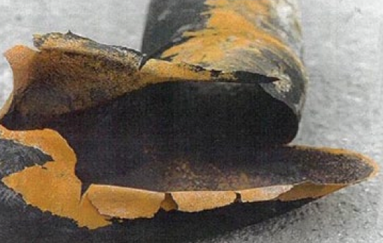
Piping failures still represent a frustrating and ongoing problem for processing plants (example in Figure 1)1. Failures are still commonly reported and contribute to large losses. In the author’s experience, piping represents the highest percentage of fixed equipment failures in petroleum refining. There are of course many factors within a pressure equipment integrity program (PEIP) that can contribute to piping integrity problems, including design issues, operating window compliance, management of change issues, etc.
This article is the second of a series of articles that will focus on one critical sub process within a PEIP that is key in managing the integrity of process piping: thickness monitoring programs for internal corrosion. These articles will discuss what constitutes an effective piping thickness monitoring process and will present several practices that may be new to some readers, but these practices have produced beneficial results in other major piping reliability programs. The first article (September/October 2012 Inspectioneering Journal) provided an overview of this process as outlined in Figure 2. This second article will discuss the considerations that factor into determining the number and position of corrosion monitoring locations (CMLs) as part of the thickness monitoring which is outlined in the highlighted (red) portion of Figure 2. A future article will focus on the type of monitoring, comparing radiographic versus ultrasonic thickness evaluation techniques.


Comments and Discussion
Add a Comment
Please log in or register to participate in comments and discussions.