FFS Evaluations
An all too familiar scenario in power plants is one in which an inspection finding occurs late in an outage and consequently, the return to service date may need to be postponed to allow time for corrective action. Historically, cracks or thinned spots were typically repaired without question. In contrast to this, the use of a fitness-for-service evaluation in this scenario has long been common practice in the petrochemical industry. Competitive forces drove that industry to run with lower safety factors and more stringent engineering evaluations early in its development. The regulated electric utility industry, however, allowed for costs to be passed on to the customer, and it was common practice to return boilers to service in "like new" condition. With the deregulation of the electric utility industry, the need to be able to run the unit safely and reliably until the next outage replaced the requirement to do so until the scheduled retirement date. Consequently, the use of the fitness-for-service (FFS) standards API 579-1 / ASME FFS-1 is increasing in the power industry. This evaluation can result in significant savings in costs and time.
The National Board Inspection Code (NBIC) published by the National Board of Boiler and Pressure Vessel Inspectors provides standards for installation, inspection, and repair and/or alteration of boilers, pressure vessels, and pressure relief devices. In recent years, the NBIC added references to the use of FFS methods found in FFS-1. Referencing of these methods was significant because it signaled that the owner was being allowed to evaluate a damaged condition instead of automatically restoring the component to like-new condition. This option represented a significant savings to the owner at a time when deregulation was fueling competition. The trend continues and fitness-for-service evaluations for situations not currently included in FFS-1 are being conducted in the same methodical approach as FFS-1. An example of such is the recent incident involving the late discovery of three broken main steam piping spring supports and a fast approaching return to service date.
Evaluation of Damaged Pipe Supports
Stress was recently requested by the operator of a large industrial plant to provide a FFS disposition for the main steam pipe at one unit. During a scheduled maintenance outage at the plant, inspectors had discovered that three variable-spring pipe supports on the steam pipe riser had cracked springs. The unit was scheduled to return to service about one week after these failed components were discovered; that is, there was insufficient time to replace the pipe supports. The plant operator urgently needed to know whether the unit could safely be returned to service with the cracked springs supporting the pipe and, if so, what the risks and consequences of further failure would be. If the damaged springs could safely remain in place for the interim, they would be replaced during the next scheduled outage several months in the future.
As is often the case in FFS assessments, our analysis and recommendations were needed immediately. Stress personnel quickly mobilized for traveling to the plant with the appropriate equipment. We also immediately began to prepare a pipe stress model based on information from the operator. A finite element analysis model of the batwing welded attachment was also begun in preparation for addressing any loading and remaining life concerns that might develop as a result of knowing the actual pipe support loads.
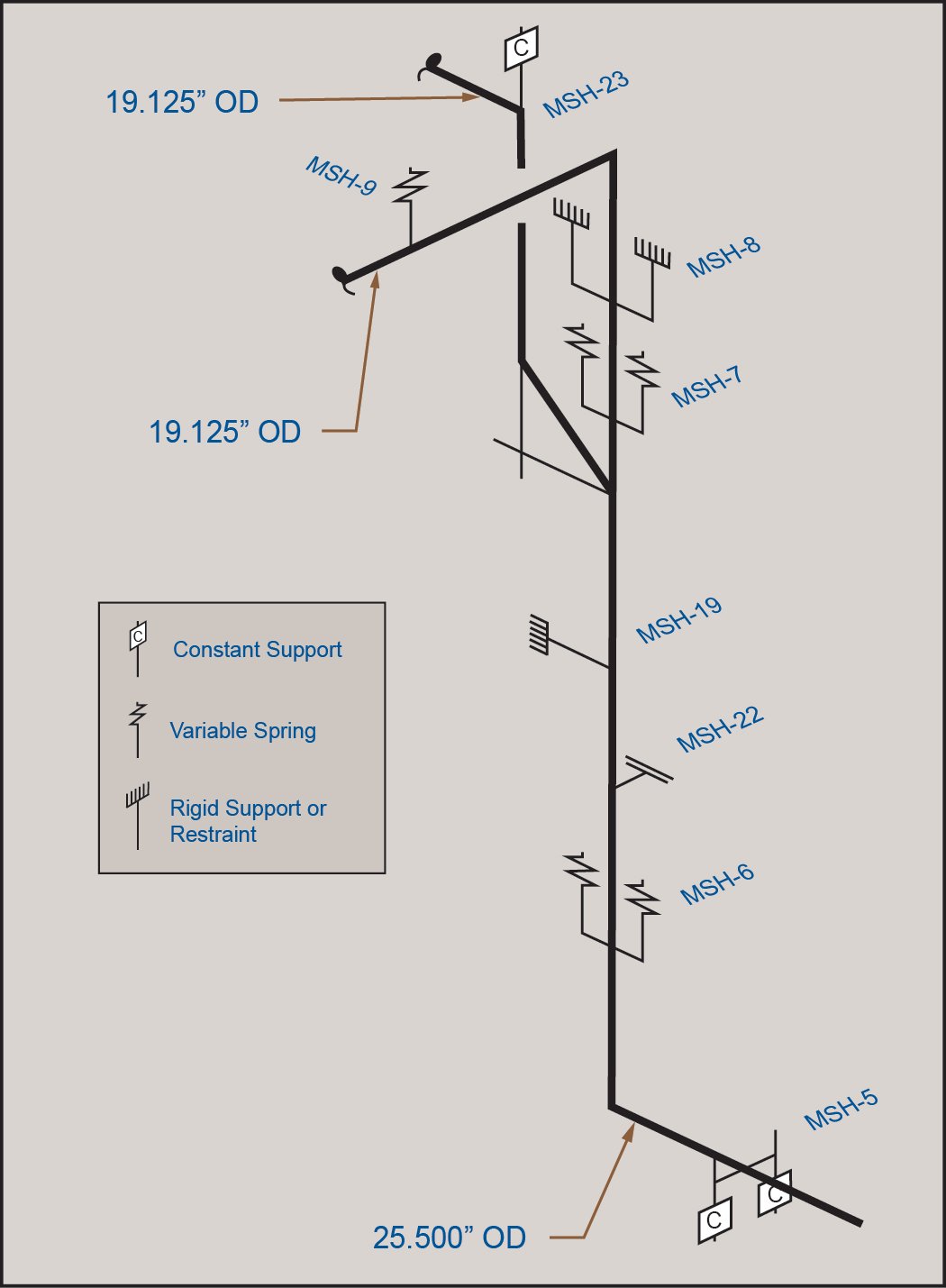
The main steam piping under consideration consisted of a 25½” OD main run with 19” branches at both the boiler and turbine ends. Three main steam spring supports (MSH-6 south and MSH-7 north and south) were determined to have cracked springs. Figure 1 shows the main steam pipe routing and pipe support locations.
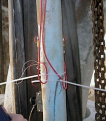
Once on site, strain gages were installed on the six hanger rods for supports MSH-6, -7, and -8 to measure strains in the riser supports. A typical strain gage installation is shown in Figure 2. The strains were measured as each pair of rods was unloaded. Support loads were calculated based on actual hanger rod diameters and measured strains. Hanger load data were used in the pipe stress model to calculate loads on the supports and piping. Pipe wall thickness was measured using ultrasonic testing (UT) and actual pipe wall thicknesses were used in the evaluation.
It was determined that the cracked springs were carrying lower loads than designed and lower than equivalent springs that were not cracked. Analysis indicated that, at the cold condition, load was being transferred to hanger MSH-23 located above the rigid support. At the hot condition, the load shifted to hanger MSH-5, the first pipe support on the lower horizontal ran below the riser. SES determined that hanger MSH-5 bottoms out after 8½” of downward thermal growth. The pipe is expected to grow about 12” downward; consequently, the remaining thermal growth beyond the capacity of hanger MSH-5 is forced upward, thereby reducing the load on the riser pipe supports in the hot condition. Although this was not the original design, it had the beneficial effect of countering the loss of support at the cracked springs. Further analysis would be required to determine the long term effect on the piping at hanger MSH-5.
Calculated stresses for the pipe and connection welds were determined to be below Code allowable stress. Our team concluded that the cracked springs did not have a significant effect on the remaining life or risk of failure of the main steam pipe.
Based on our recommendations, the operator returned the unit to service on schedule. After the subject pipe was stabilized at its operating temperature of 1000°F, loads were again measured in the field for the same three pipe supports. These hot loads were then compared to the Code stress model results to further calibrate the model. Predictions were sufficiently close to measured loads, and the original conclusions remained unchanged.
Finally, we prepared recommendations regarding replacing the cracked springs in the future, balancing the loads, and possibly redesigning the support system.


Comments and Discussion
There are no comments yet.
Add a Comment
Please log in or register to participate in comments and discussions.