Abstract
Most common radiographic practices for circumferential weld testing are single wall and double wall techniques with certain variations in technique details. Different Codes deal with the number of exposures required and applicability of the technique for different combinations of pipe diameter and wall thickness. However, there are certain geometries where these conventional radiography techniques are not applicable, mainly because the weld is superimposed on some structural material inside the tube or pipe. This material obstructs the weld image. Pipe welds containing small diameter concentric pipe or structural material inside the pipe and end plug to tube weld are typical examples. Such geometries can be better radiographed in tangential orientation. Coverage of welds in each exposure depends upon the combination of wall thickness and diameter. Depending on the diameter and wall thickness, different variations of the technique can be selected. This paper describes the experience gained in tangential radiography techniques and their effectiveness in detecting various defects.
Introduction
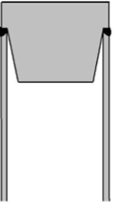
Radiography produces two-dimensional images of engineering components under test. Such components are not always simple in shape. Sometimes background is more complex in nature than a piece of plate. Arrangement of exposure set up is governed by shape of the job, penumbra, back scattering phenomenon, radiation intensity etc. For most commonly encountered weld configuration, i.e. longitudinal welds and circumferential weld in spherical and cylindrical geometry, ASME codes provides guidelines for arrangement of exposure setup, number of exposures required for complete weld coverage and provisions for penetrameter placement. But there are certain weld geometries, where conventional radiographic technique may not work satisfactorily. In such cases special techniques are to be adopted. An end plug to tube joint is one such example case encountered in chemical, nuclear and petroleum industries, where a thin wall tube is welded to solid end plug (figure 1). Evaluation of weld integrity for such weld joint configuration is important, as failure of welds leads to leaking of fluid into the outer atmosphere. They are difficult to radiograph because plug material is superimposed on the thin weld making defect detectability by the conventional double wall double image super imposed technique (DWDI) is very poor.
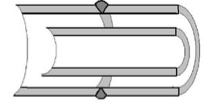
Another situation where the conventional technique is not fruitful, is in the case of a pipe weld enclosing one more concentric pipe as shown in figure 2 . Due to presence of the inner pipe the conventional double wall double image(DWDI) or double wall single image(DWSI) is not useful. Therefore the tangential technique is the only radiography option at the inspector’s hand. In our laboratory we practice tangential the radiography technique with different variations for different diameters and materials.
Tangential Radiography
Traditionally tangential radiography is used to detect internal and external corrosion attack on large dia. insulated and non-insulated steel pipe. These pipes can experience various sorts of degradation such as erosion, corrosion, corrosion, erosion, etc. over time. To ensure reliable and safe performance, wall thickness of the pipe is monitored typically with straight beam point ultrasonic thickness measurements or area scanning. Though point ultrasonic testing provides accurate data of pipe wall thickness , it requires removal of the insulation layer for periodic inspection, which is costly and does not have a high likelihood of detecting localized corrosion. Therefore tangential radiography is used as an alternative choice. Tangential radiography is a technique to image the circumferential edge of pipe or tubes. For large diameter pipe, the radiation beam is centered towards the edge of the pipe so the radiation beam is essentially at a tangent to the pipe edge. For tube, the diameter is so small compared to source to film distance (SFD), all the radiation beam reaching the tube can be considered perpendicular to the tube. In this case the edge of the tube is interpreted instead of top and bottom wall. The radiation path at the extreme edge is zero and increases towards center due to presence of curvature. Hence the selection of exposure parameters is governed by the edge. Energy or kV is decided by the vertical penetration path at a desired depth of interpretation. The penetrameter is kept on a separate block near the job. The block thickness is equal to the maximum penetration path at the edge. In figure 3, a pipe of outer radius R is considered for tangential radiography. Let ‘t’ be wall thickness of tube or pipe. Also radiography is done to interpret the single wall. Hence depth of interpretation is ‘t’. The energy (kV) selection is based on radiation path ‘Dmax’ at a depth of ‘t’ from the edge.


Comments and Discussion
There are no comments yet.
Add a Comment
Please log in or register to participate in comments and discussions.