Editor's Note
Especially for advanced NDE, including volumetric methods such as RFEC, we recommend using a valid and well thought-out qualification demonstration testing program. This program should test hardware, technique and operator with parameters similar to the field testing conditions, that they will perform in a manner satisfactory to assure, perhaps with complimentary NDE and/or engineering analysis, results leading to a safe, realistic remaining life prediction. The following was excerpted from the formal, final report. The IJ editorial staff printed only those areas that relate to mechanical integrity for the benefit of the Inspectioneer. References are noted exactly as they appear on the USCSB document, entitled," U.S. Chemical Safety and Hazard Investigation Board, Investigation Report, Chlorine Release July 20, 2003" (this report also includes information for a hydrofluoric acid release and antimony pentachloride exposure). We recommend that readers, before making any final conclusions read the full report which can be found on the world wide web at http://www.csb. gov/completed_investigations/docs/CSBHoneywellFinalReport.pdf
Report...
Executive Summary
On July 20, 2003, a release of chlorine gas from the Honeywell International, Inc. (Honeywell) chemical plant in Baton Rouge, Louisiana, resulted in injuries to seven plant workers and issuance of a shelter-in place advisory for residents within a 0.5-mile radius. On July 29, 2003, a 1-ton cylinder at the same plant released its contents to the atmosphere, fatally injuring a plant worker by exposing the worker to contaminated antimony pentachloride. On August 13, 2003, two workers at the plant were exposed to hydrogen fluoride requiring hospitalization for one of those workers.
The U.S. Chemical Safety and Hazard Investigation Board (CSB) incident investigation determined root and contributing causes for the three incidents. An overall analysis revealed common deficiencies in the following management systems:
- Hazard analyses did not ensure a review of all equipment, procedures, and likely scenarios. The safeguards listed were generic and, in many cases, relied too heavily on administrative procedures.
- Nonroutine situations were not always recognized and reviewed to ensure that work could proceed safely.
- Work practices at the plant did not always strictly follow written operating procedures.
CSB determined that guidance and standards for design and maintenance of positive pressure control room systems were lacking in the U.S. chemical industry. CSB also found that manufacturers and users of hydrogen fluoride could benefit from sharing of best practices on draining equipment and maintenance operations for hydrogen fluoride.
CSB makes recommendations to Honeywell International, Inc.; the Baton Rouge facility; Chemical and Metal Industries; American Society of Heating, Refrigeration, and Air Conditioning Engineers; East Baton Rouge Parish Office of Homeland Security and Emergency Preparedness; Baton Rouge Fire Department; and Hydrogen Fluoride Industry Practices Institute........
2.3.1.1 Cooler History
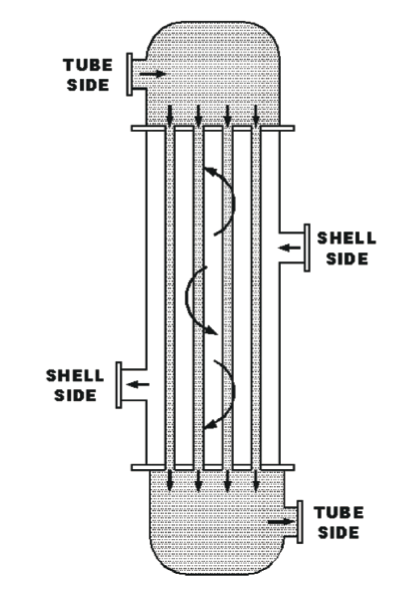
The vertical chlorine cooler was an American Society of Mechanical Engineers (ASME)-code certified pressure vessel14 built and installed in 1986. It had a fixed tube design with 0.109-inch-thick tube walls.
Figure 7 shows key milestones in the history of the chlorine cooler.
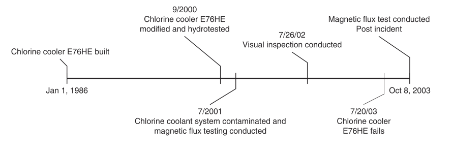
In September 2000, modifications were made to the exchanger shell side vents and drains. These modifications, which were made in accordance with the National Board of Boiler and Pressure Vessel Inspectors and ASME code requirements, were certified and inspected by qualified contractors.
In July 2001, an incident in the G-143a reactor contaminated the coolant system with catalyst and other reactor contents. The system was then drained and refilled, and all associated equipment was tested to determine if the contamination caused any damage. No damage was found in the chlorine cooler. As a part of the Honeywell mechanical integrity program, the chlorine cooler was inspected every year using visual external inspection and inspected every two years using magnetic flux leakage testing. Magnetic flux leakage is an NDT method that relies on magnetism to inspect ferromagnetic materials such as carbon steel. External visual and magnetic flux leakage inspection of the cooler in 2001 revealed no plugged tubes, measurable defects, or wall thinning.
2.3.1.2 Post-Incident Testing
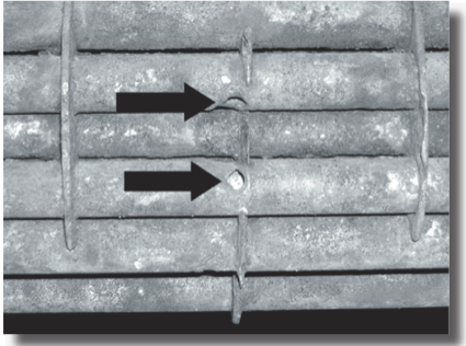
Following the July 20 incident, the chlorine cooler was cut open and inspected. Visual inspection revealed three holes in the tubes and a buildup of corrosion products at the bottom (two holes are shown in Figure 8). All corrosion products and the holes were found in the lower section of the cooler; the holes originated on the outside surface of the tubes (refer to Figure 2). One hole was crescent shaped and about 0.5 inch long, while the two other holes were about 0.25 inch in diameter and approximately 5 inches higher on adjacent tubes. After the visual inspection, two holes were confirmed by magnetic flux testing performed by a Honeywell contractor; however, the third hole's test results showed only significant wall thinning.
Following agreement with CSB and OSHA on testing protocols, Honeywell hired a laboratory to conduct additional failure mode testing of the chlorine cooler.
The laboratory was unable to determine conclusively what the failure mechanism was, based on physical evidence alone. After further study, the laboratory proposed that damage on one tube might have been caused by the September 2000 modifications and exacerbated by the July 2001 contamination incident. Appendix A provides additional details on this failure theory.
2.3.1.3 Analysis
Upon referral by ASNT, CSB contacted the Electric Power Research Institute (EPRI).16 EPRI has studied several NDT methods-magnetic flux, remote field eddy current, and magnetically biased eddy current-and demonstrated that the different NDT techniques have different strengths and weaknesses for given applications. Specifically, EPRI has concluded that magnetic flux may not detect all defects in thick carbon steel tubes (such as the 0.109-inch tube walls in the chlorine cooler).17 EPRI cautions that tube thickness and material of construction should be considered in choosing the most appropriate NDT method (Dau and Kryzywosz, 1990).
A magnetic flux leakage inspection in October 2003 followed the July 20, 2003 incident. Two of the three holes were identified by that inspection, but the third showed only as wall thinning. This finding suggests that either the methodology or the testing apparatus is less than adequate to positively detect thinning and failure of the 0.109-inch tube walls.
In light of this incident and CSB findings, NDT programs should be periodically reviewed and modified based on experience and advances in NDT technology. Although many companies use magnetic flux testing, this incident showed that in cases involving coolers such as the chlorine cooler in the Baton Rouge plant, this testing method does not appear to be the best choice...
2.5 Key Findings
- The G-143a chlorine cooler tubes failed, releasing chlorine into the G-143a coolant system.
- The materials of construction for the G- 143a coolant system pump were not compatible with chlorine; therefore, system components failed, releasing chlorine to the atmosphere.
- Incident timelines show a 31-minute delay between the Honeywell report of a level III incident and the Baton Rouge Fire Department activation of the shelter- in-place alert.
- Although the chlorine cooler was constructed of materials suitable for its intended use, inspection and testing were the only layers of protection against failure.
- The chlorine cooler had been inspected in 2001 using the magnetic flux NDT method. Test results then showed no flaws. Magnetic flux testing done after the incident, when three holes were present, showed two complete holes through walls, but only wall thinning at the location of the third hole.
- EPRI has demonstrated that magnetic flux testing may not be the best NDT method for ferrous (such as carbon steel) coolers with tube walls as thick as those in the chlorine cooler (0.109 inches).
- The G-143a PHA did not identify the potential for chlorine leaking into the coolant system.
- The PHA on a similar process in the same facility (G-113 R1) identified the possibility of chlorine leaking into the coolant system but did not evaluate the consequences.
- The MOC review (including the associated hazard analysis) conducted when the chlorine feed system was modified to allow use of railcars (at a capacity of 180,000 pounds) in addition to ton cylinders (at a capacity of 2,000 pounds) did not identify a need to integrate the chlorine railcar and G-143a shutdown procedures.
- The G-143a shutdown sequence and procedures did not include isolation of the chlorine railcar.
- Chlorine released from the cooler entered the positive pressure control room through holes or gaps in the HVAC ductwork.
- The design of the positive pressure control room system was not adequate for protecting operators long enough to allow them to identify the source of the chlorine leak and shut down the G-143a process.
- The Omni unit control room was designed to be positive pressure, but the positive pressure system was not routinely inspected or maintained.
- Previous incidents of chlorine entering the Omni control room had occurred. In those cases, actions were taken to eliminate the source of odors; however, no formal investigation was conducted to determine how the chlorine entered the positive pressure control room.
- There are no standards or guidance applicable specifically to design and maintenance of positive pressure control rooms for the U.S. chemical industry.
2.6 Root and Contributing Causes
2.6.1 Root Causes
- The Honeywell Baton Rouge plant management systems did not protect against failures in the chlorine cooler.
The Honeywell mechanical integrity system failed to identify problems with the chlorine cooler prior to its failure. Annual inspections prior to the incident did not show any flaws in the cooler tubes. Honeywell had no additional measures in place to protect against cooler failure, such as monitoring for chlorine leaks. Because the mechanical integrity system was relied upon exclusively, a failure in the cooler resulted in chlorine contacting incompatible materials in the coolant system and releasing chlorine to the atmosphere.
2. The consequences of chlorine entering the coolant system were not fully evaluated.
The Honeywell G-143a PHA was too general and did not identify the potential for chlorine leaking into the coolant system. The chlorine feed system was considered as a whole. However, because there was no consideration of potential hazards in individual pieces of equipment, the possible failure of the chlorine cooler was not evaluated. Although the possibility of a leak in the chlorine feed system was considered, general safeguards such as design, maintenance, and procedures were listed as adequate to prevent or respond to a leak.
Furthermore, the potential impact of contamination of the coolant system was never fully evaluated-neither during the G- 113 R-1 PHA that did identify the possibility of coolant system contamination nor after a July 2001 incident that contaminated the system...
2.7 Recommendations
Honeywell Baton Rouge Facility
- Revise inspection and testing procedures to include effective methods for detecting and preventing leaks in coolers that use chlorine. These procedures should include the use of appropriate NDT methods. (2003-13I-LA-R1)...
Final editors note: More recommendations, not directly pertaining to NDE were included in this report. We recommend you read the complete report which can be found at http://www.csb.gov/completed_ investigations/docs/CSBHoneywellFinalReport.pdf


Comments and Discussion
There are no comments yet.
Add a Comment
Please log in or register to participate in comments and discussions.