The need for TOFD
The ultrasonic Time of Flight Diffraction (TOFD) technique was developed for the UK nuclear industry during the 1970s to provide a method for measuring the height of planar flaws. TOFD is now generally recognised as the most accurate ultrasonic technique for measuring the height of embedded planar flaws (eg. cracks, lack of fusion, etc.) that lie perpendicular to the surface.
Commercial TOFD systems (eg. MICROPLUS) have been available for some time from a range of suppliers. (An independent buyers’ guide can be found on the website of the British Institute of Non- Destructive Testing at www.bindt.org. At present, national standards for the application of TOFD exist. However, no standardised acceptance criteria have been agreed upon for pre-service (fabrication) inspection. For pre- service inspection, TOFD is therefore commonly used with weld flaw acceptance criteria derived by engineering critical assessments (ECA) as described in BS7910.
How does TOFD work?
Most ultrasonic techniques rely on receiving reflections from flaws, even if only from particular facets of the flaws. TOFD detects cracks using the signals diffracted from the flaw’s extremities (tips). Two angled compression wave probes (typically between 2 to 10MHz frequency) are used in transmit-receive mode, one probe each side of the weld. The beam divergence is such that the majority of the thickness is inspected, although, for thicker components, more than one probe separation may be required. When the sound strikes the tip of a crack, this acts as a secondary emitter that scatters sound out in all directions (some in the direction of the receiving probe), Fig.1.
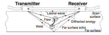
A ‘lateral wave’ travelling at the same velocity as the compression waves, travels directly from the transmitter to the receiver. The time difference between the lateral wave and the diffracted signal from the flaw provides a measure of its distance from the scanned surface. If the flaw is large enough in the through-wall (height) dimension, it may be possible to resolve the tip diffracted signals from its top and bottom, thereby allowing the through wall height of the flaw to be measured.
Signal processing of UT information
Due to the low amplitude of the diffracted signals, TOFD is usually carried out using a preamplifier and hardware designed to improve signal-to-noise performance. As the probes are scanned along the weld, the A-Scan signals are digitised, Fig.2.


Comments and Discussion
There are no comments yet.
Add a Comment
Please log in or register to participate in comments and discussions.