| This article is part 1 of a 2-part series. |
| Part 1 | Part 2 |
Introduction
Corrosion and fouling in HF Alkylation Units are closely linked to feed quality and operating conditions. This article outlines the relationship between key operating parameters and corrosion that has been used to develop a set of guidelines to define an operating envelope. These guidelines have been used to benchmark operating units and to help maintenance and inspection groups understand how corrosion is directly affected by operating parameters. An example where this methodology has been used to troubleshoot operating problems is included. A web-based data collection system has been used as a tool to build a database of actual operating conditions found in the unit, and the corresponding problems or damage observed.
The methodology described in this article was developed to help maintenance and inspection groups gain a better understanding of the manner in which corrosion is directly affected by operating parameters. Although much of this information is available to process licensees, it is generally not disseminated among the various disciplines in the refinery in a manner which can be clearly understood and applied.
Significant damage can occur when operating parameters drift outside recommended limits, or when licensor-recommended operating procedures are not followed. Except where noted, these issues apply to both UOP and Phillips licensed processes (1).
There has been considerable interest over the past several years in reducing the risk of operating HF Alkylation (HFA) Units (1), but little information has been published on the effects of operating conditions. Most of the recent efforts have focused on ancillary issues including galvanic couples and the effect of residual elements in steel (2-7), and materials of construction
guidelines (8-11), usually based on laboratory test data and/or exposures in anhydrous acid.
A noteworthy reference is the detailed work published by H. Helle (12). This book contains significant information on corrosion and the effects of operating parameters, some of which is reflected in the discussions in this paper. Other relevant articles describing experience with HFA units identify the types of corrosion problems (13-16); areas of vulnerability; and the use of hydrogen probes to monitor hydrogen activity (17).
Several terms that are unique to HF alkylation units and that are used throughout this article are defined below.
- Acid Concentration is the concentration of hydrofluoric acid based on its water content. For example, a solution of 98 wt% HF concentration indicates that there is 2 wt% water in the acid.
- ASO refers to acid soluble oils which, as the term implies, are soluble in HF. ASO is comprised of a number of compounds including short-chain and long- chain sulfur-containing polymers with different boiling ranges that promote corrosion in the unit.
- Acid Strength is a measure of the ‘purity’ of the acid considering dilution effects in addition to water. Components that reduce acid strength are water, ASO, dissolved reactants and organic fluorides.
- Organic Fluorides are combined fluorides that are produced in secondary reactions including ethyl fluoride, propyl fluoride and butyl fluoride. They are always present in measurable quantities in the product streams, the extent to which is dependent on a number of operating parameters including acid strength and reactor temperature.
Simplified Process Description
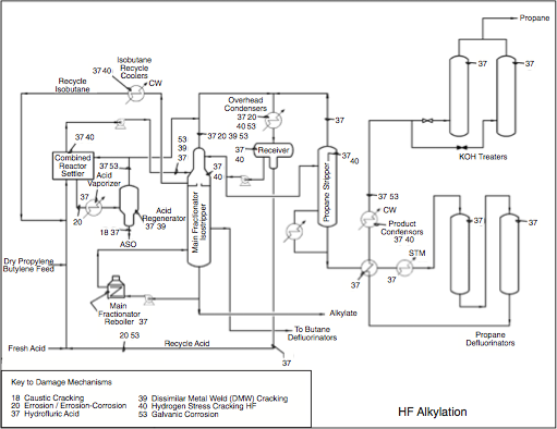
The HFA unit can be divided into three main sections: Reaction, Fractionation, and Defluorinating / Alumina Treating. A detailed description of the HFA process is outside the scope of this paper, but in simple terms, the purpose of the unit is to react an olefin feed with isobutane (iC4) in the Reaction Section in the presence of the HF Acid catalyst to produce alkylate (Figure 1). Prior to entering the Reaction Section, the olefin and isobutane feed are treated to remove water, sulfur and other contaminants.
In the Fractionation Section, alkylate is separated from excess iC4 and acid catalyst through distillation. Unreacted isobutane is recovered and recycled back to the Reaction Section to mix with the olefin feed. Propane is a major product of the distillation process. Some amount of normal butane (nC4) that has entered with the feed is also withdrawn as a side product.
Propane and butane that have not been separated from the treated olefin pass through the unit. Although they do not participate directly in the reactions, and adversely impact product quality, they provide an avenue for organic fluorides to leave the unit. The propane and butane product streams are processed in the Deflourinating Section to remove combined fluorides and any trace acid that may be present due to mis-operation.
How Operating Conditions Affect Corrosion
Corrosion and fouling are often linked to lack of attention to key operating parameters and control points. In this respect, feed treating is the first line of defense in keeping contaminants including sulfur, water, diolefins and other compounds, out of the unit. The effect of these contaminants as they pass through each of the three main sections of the HFA unit is described below.
Feed Preparation and Feed Treating
Feed treating is the first line of defense in keeping contaminants out of the HFA unit. It cannot be emphasized enough that a significant portion of corrosion and fouling problems are a direct result of contaminants which have a cascading effect on operations throughout the unit.
- Feed Composition is a function of the upstream feedstock producers. It is comprised of a combination of butylene, propylene, and sometimes amylene olefins. Most of the olefin feed originates in the FCC or coker gas plant as depropanizer bottoms and/or debutanizer overheads. The iC4 may come from several sources including a saturate gas plant deisobutanizer, butane from an FCC depropanizer overhead liquid, a Crude unit deisobutanizer overhead, and purchased iC4.
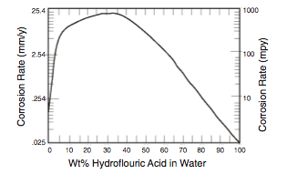
- Water is a major contaminant that promotes corrosion in several ways (2). First, it is widely recognized that corrosion is a function of HF acid concentration and temperature, and that high rates of corrosion (>>100 mpy [ >>2.54 mm/yr] ) can occur as the acid becomes more dilute (Figure 2).
Second, the presence of water reduces acid strength and contributes to the formation of corrosive ASO. Both the water and the ASO must be removed through regeneration of the acid which is destructive in its own right as discussed later.
Removal of water from the feed is usually accomplished through a combination of methods including distillation drying, coalescers and/or sand filters. The last vestiges of water are removed in the final feed drying step using alumina treating or molecular sieves which can reduce the water content of feed streams to the 1 to 5 wppm range. A moisture analyzer or conductivity meter should be used to continuously monitor water.
- Sulfur is one of several other contaminants that affect corrosion on the unit. Sulfur in the feed reduces the acid strength by reacting to form light ASO/ polymer that is difficult to remove in the acid regenerator and contributes to acid loss and corrosion. The sulfur compounds most commonly found in FCC olefin feed are H2S, mercaptans and small quantities of carbonyl sulfide (COS). Their effect is independent of molecular form, so that the total sulfur content of the feed should be used in the analysis.
The goal of sulfur removal should be to reduce it as low as reasonably possible. Although licensors may suggest starget levels of 20 wppm maximum, it is far better to target a maximum of 5-10 wppm in the olefin feed and Isobutane make-up, normally achieved with a combination of amine and caustic treating.
The effectiveness of sulfur removal is a function of the ever changing configuration of the upstream units which can affect the level of sulfur in the FCC reactor feed. Some of the H2S will be removed in the FCC gas plant and/or amine treating, often followed by a caustic scrubber. The H2S tends to stay with the propane so that the degree of H2S removal in the FCC gas plant will be less complete with a higher proportion of C3 olefins in the feed.
Effective caustic treating will remove mercaptans. If required, excess COS can only be removed through amine treating in the H2S removal unit, and the degree of removal depends on the type of amine used. Otherwise, specially designed COS treatment facilities are required.
- Diolefins such as butadiene enter with the olefin feed and react to form ASO. Diene levels in olefin feed streams have been increasing with the increase in FCC Reactor severity and should be periodically monitored to ensure that they do not exceed recommended limits in the feed. Refineries that treat olefins with a selective hydrogenation process effectively eliminate dienes in the olefin feed to the HFA Unit.
Oxygenate contaminants including MTBE, methanol, acetone and DME may be present in the olefin feed depending on upstream configuration. The effect of oxygenates is to reduce acid strength. DME is usually found in refineries that have an MTBE or TAME unit. It is particularly difficult to remove in the acid regenerator since it goes overhead with the acid vapors, and must be intentionally dumped out the bottom of the regenerator, resulting in higher acid losses.
- Oxygen dissolves in, and tends to stay with, the HF acid and accelerates corrosion of carbon steel, Alloy 400 and copper alloys. It can enter the unit through a number of sources including imported feedstocks, FCC wet gas compressors, improper operation of a caustic treating unit, or improperly charging fresh acid into the unit, particularly if oxygen-contaminated nitrogen is used. Oxygen is extremely difficult to monitor once it gets into the unit, and can only be removed through the venting of non-condensables into the flare header.
- Ethanes and Lighter molecules (methane, ethane, ethylene and non- condensables) enter the unit due to inadequate feed preparation, usually as a result of improper operation of the FCC Deethanizer, or in contaminated isobutane which has not been fractionated to remove these compounds. The primary effect is to collect and build up pressure in the fractionating towers. Removal is achieved through venting into the relief header, however, this contributes to corrosion of the ARN/Relief Gas Scrubber and acid relief system.
Ethylene reacts to form organic ethyl fluoride and leaves the unit with the propane.
- Nitrogen compounds including amines, acetonitrilies and acrylonitriles lower the acid strength and must be removed through acid regeneration. They have also been reported to provide a potential for ammonium fluoride plugging. Limits on amines or nitrogen compounds are not well established but many can be effectively removed by caustic treating.
- Other Contaminants exist that can lower acid strength or upset feed treating and drying equipment but are not normally monitored unless there is a problem. These include arsenic, C6+ hydrocarbons and caustic carryover. Arsenic has been linked with blistering and HIC/SOHIC damage in HFA units.
Reaction Section
As mentioned previously, the olefin feed and iC4 are combined with HF acid in the Reaction Section to produce alkylate (usually iso-octane). This is also where the major HF inventory is located. Mixing of the olefins and iC4 is achieved through proprietary mixing/contacting methods but always involve a shell and tube heat exchanger to control the temperature of the reaction mix. Excess HF is removed by gravity separation from the reaction mix in a settling-type of vessel identified by terms such as the ‘acid settler’, ‘mixer settler’ or ‘recontactor’, etc. The hydrocarbon rich stream is sent to the Fractionation Section, described later.
- Acid Water Content. The water content of the circulating acid is normally maintained in accordance with licensor recommendations, and generally does not exceed 2%, depending on the type of unit. With higher amounts, carbon steel corrosion rates increase and the morphology of the protective iron fluoride scale changes, and becomes softer and less protective. Particles of suspended iron fluoride scale become dislodged and travel with the process streams resulting in fouling of heat exchangers and plugging of trays.
It is important to realize, however, that the water content is normally measured from an acid sample taken from the main acid inventory in the Reaction Section, and this is not necessarily representative of local equilibria in disparate sections of the unit. The redistribution and solubility of water in the hydrocarbon stream in the fractionator feed is further affected by the reaction temperature and is a complex combination of factors depending on acid strength and ASO content.
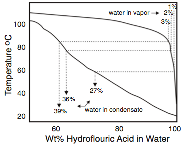
In addition, the water content of the first drop of acid to condense from a process stream is much higher than the nominal water content of the condensed phase. For acid streams with 1% to 3% water, the binary phase diagram for HF-H2O shows that the first drop of acid to condense contains 10 to 20 times as much water as the vapor from which it condenses (Figure 3). This phenomenon was considered in the investigation of the effects of residual elements in steel using corrosion tests in solutions of 60% HF. This concenrtation was used to represent concentrations of nearly anhydrous acid streams that are condensing in an alkylation unit16.
HFA units practicing internal regeneration in the Isostripper may be susceptible to high rates of corrosion in the Isostripper tower if process control parameters are not meticulously followed to keep water below 1% at all times.
- Acid Strength. The importance of acid strength has been alluded to throughout this paper. Acid strength is a measure of the purity of the acid and normally ranges between 83% and 90%. Components that reduce acid strength are water, ASO and dissolved reactants. Low acid strength contributes to further formation of acid ASO and organic fluorides. From a corrosion standpoint, it is preferable to operate in the higher end of the range at all times, preferably above 88%. Operation below 80% can result in an acid runaway in which the entire acid inventory converts to ASO and organic fluorides.
- Reactor Riser/Acid Settler Temp. The shell and tube heat exchanger referred to as the ‘Reactor’ (UOP) or ‘Acid Cooler’ (Phillips) helps to control the reaction temperature of the reaction mix. Reaction temperatures vary from one refinery to another but range from approximately 60oF (16oC) in colder climates to 105oF (41oC) or higher. The extremes of this range are outside the normal recommended operating limits. Organic fluoride production can become an issue as temperatures are reduced. If the reaction temperature is too high, the rate of ASO formation increases.
- Acid Rerun (Phillips) / Acid Regeneration (UOP) Section. A slip stream of HF is fed to the Acid Rerun or Acid Regeneration tower to purify the acid by removing water and ASO. The two licensor methodologies are slightly different but both employ hot isobutane vapor to strip off the HF vapors. The water that remains forms a corrosive acid phase known as a constant boiling mixture (CBM) comprised of 62% water and 38% HF.
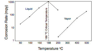
Much of the HF stripping tower and associated piping is usually constructed from solid or clad Alloy 400 for this corrosive service. Corrosion rates of Alloy 400 increase significantly above about 300oF (140oC). In order to minimize corrosion, the Acid Vaporizer (Phillips) outlet temperature should not exceed limits prescribed by the licensor. Steam temperature should also be limited to minimize corrosion of the bundle, and stripping isobutane should be limited to 370oF (188oC).
In the UOP Acid Regenerator Towers, superheated Isobutane stripping vapors should be limited to 450oF (232oC). Operating procedures should be in accordance with licensor recommendations to prevent corrosion of the bottom tray.
The bottoms from these towers consists of CBM and polymer (alky tar), with some dissolved acid, which are separated and neutralized with KOH. These two streams are extremely corrosive if not neutralized properly. Corrosion rates of inadequately neutralized CBM are measured in “miles” per year. In the polymer stream, small quantities of combined fluorides may decompose to liberate free acid if the neutralized polymer is reheated in steam-traced piping or equipment.
Some of the lighter ASO compounds can vaporize in the regenerator and return back to the process with the HF. The regenerator may need to be run at a lower temperature to get rid of them, resulting in higher acid losses.
Fractionation Section
It is important to note that HF is soluble in isobutane and its solubility increases with increasing temperature. The hydrocarbon-rich stream downstream of the acid settling drum consists of alkylate (i.e. reacted olefin), excess isobutane, propane, normal butane, ASO, and combined fluorides. Theoretically, the total acid content of this stream is <1%, based on soluble HF content of the major components.
- Acid Carryover. The feed to the first fractionation tower downstream of the acid settling drum is designed to contain only acid that is soluble in iC4. The remaining acid is heavier than the bulk hydrocarbons and is separated out to in an acid boot. The reality is that some entrained acid may carry over into the fractionation section, contributing to corrosion of the feed line, tower top, trays and overhead line. In extreme cases, excess acid carryover can result in free acid dropping further down the tower.
- Recycle iC4 Purity. Recycle iC4 is recovered from the Fractionation Section, primarily from the top or side of the first fractionation tower, or other locations depending on unit configuration. The purity of the recycle iC4 is an important parameter that is closely monitored and controlled. Although maximum achievable purity is limited by the tower design and internals, every reasonable effort should be made to maximize purity.
Recycle isobutane is returned back to the Reaction Section. As iC4 purity is reduced, the amount of organic fluorides formed increases in the acid settler effluent and product streams. In addition, in order to maintain a constant isobutane/olefin (I/O) ratio, operators may increase recycle flow as the iC4 purity drops. Higher flow rates may promote acid carryover. The presence of “C6 + heavier” impurities in the isorecycle may be an indication of tray fouling in the tower.
As mentioned previously, iron fluoride is a product of the corrosion process and it is not unusual for the fluoride scales to return to the towers with the reflux and lay down on the trays or foul reboilers. Significant deposition may lead to accelerated tower fouling, impacting fractionation and resulting in the inability to maintain iC4 purity.
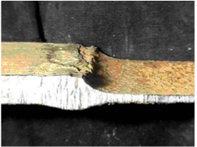
- Fractionator Feed Temperatures should be monitored, especially those towers that receive feed from the acid settler or any other overhead receiver with an acid boot. Feed lines operating above 150oF (66oC) should be monitored for corrosion; upgrading to Alloy 400 may be required if corrosion rates are excessively high or unmanageable. Several major incidents have occurred as a result of ruptured feed lines operating above this temperature. Some, but not all, of these failures have been a result of high residual elements (%Cu + %Ni +%Cr) in piping components (Figure 5).
As temperature increases above 150oF (66oC), or if acid carryover is suspected, the tower top, trays and overhead line may experience higher rates of corrosion. These locations should also be closely monitored by inspection or upgraded to Alloy 400 for improved corrosion resistance.
- HF Stripper / Propane Stripper is the final distillation step that is used to strip remaining HF from the propane. The propane bottoms product may become contaminated with free acid and corrode the bottom of the tower and outlet piping if it is not run properly. Tower operation should be in strict accordance with licensor-recommended operating guidelines to prevent acid carryunder to the Defluorinating Section.
Defluorinating / Alumina Treating Section
Propane, butane and sometimes alkylate are treated to remove free acid and/or organic fluorides depending on the end use of the product. The removal of organic fluorides is accomplished by vaporizing the fluid and contacting it with activated alumina in the alumina treaters. The combined fluorides are decomposed into HF, water and hydrocarbon.
Effluent from the alumina treaters is cooled and condensed, and contacted with solid KOH pellets to remove free acid. Some units do not have alumina treaters, and the combined fluorides will form HF acid if the LPG is subsequently combusted or heated in a reboiler (3).
Free acid should never be present in the alkylate and is a sign of major operational problems. However, alkylate normally does contain measurable levels of combined fluorides which should be removed if the alkylate is fractionated further, or if present in excessive levels.
- Alumina Treaters / Defluorinators are subject to HF acid corrosion when the alumina is spent, resulting in corrosion and/or HIC damage of the defluorinating vessels, as well as corrosion of downstream piping and exchangers. Most HFA units utilize two propane defluorinators operated in a ‘lead-lag’ mode. The defluorinators should be closely monitored to determine when the alumina needs to be changed out. A properly functioning system should have less than I ppm total fluoride in the product.
- KOH Treaters are used to remove any remaining free acid in the product streams. The propane stream from the Defluorinators/ Alumina Treaters to the KOH Treaters contains trace acid which will form a separate water phase if cooled below the water dewpoint, and corrode carbon steel. Propane effluent from the propane condenser should be monitored for corrosion and may need to be upgraded to Alloy 400 if corrosion of steel is excessive.
This is the end of Part 1. Part 2 will complete this topic with benchmarking results and summary and conclusions.
Notes
- Two major licensors of the HF Acid Alkylation process are UOP and Conoco Phillips. Explanation of Terms
- HFA units are constructed almost entirely of carbon steel, with some Alloy 400, and other alloys in some locations. All references to corrosion in this paper apply to carbon steel except where indicated.
- Organic fluorides liberate HF in the reboilers. They do not react with water to form free HF but thermally crack to form HF above about 150oF, depending on the chain length of fluoride, and may contribute to corrosion in deadlegs and relief valve inlet lines.
References
- API Recommended Practice 751, Safe Operation of Hydrofluoric Acid Alkylation Units, 2nd Edition, American Petroleum Institute, Washington, D.C., 1999.
- H.H. Hashim and W.L. Valerioti, Corrosion resistance of carbon steel in HF alkylation service, Materials Performance, Nov 1993, p 50.
- W.K. Blanchard and N.C. Mack, “Corrosion results of alloys and welded couples over a range of HF concentrations at 125oF”, Corrosion/92, paper #452, (Houston, TX, NACE International, 1992).
- O. Forsen, J. Aromaa, M. Somervuori and M. Tavi, Materials performance in HF alkylation units, Corrosion/95, paper #342 (Houston, TX, NACE International, 1995).
- G. Chirinos, S. Turgoose and R.C. Newman, Effects of residual elements on the corrosion resistance of steels in HF, Corrosion/97, paper #513, (Houston, TX, NACE International, 1997).
- L.Penuela and J. Chirinos, Inspection program evaluates HF Alkylation carbon steel piping, Oil and Gas Journal, May 31, 1999, p. 55.
- A.C. Gysbers et al, “Specification for Carbon Steel Materials for Hydrofluoric Acid Alkylation”, Corrosion/03, paper #651, (Houston, TX, NACE International, 2003).
- “Materials of Construction Guideline for Anhydrous Hydrogen Fluoride”, The Hydrogen Industry practices institute, subsidiary of the Chemical Manufacturers Association, Washington, DC, revised January 19, 1995.
- NACE Technical Committee Report 5A171, “Materials for Receiving, Handling and Storing Hydrofluoric Acid”, (Houston, TX, NACE International, 2001).
- J.R. Crum et al, Characterization of Corrosion Resistant Materials in Low and High Temperature HF Environments, Corrosion/99, paper #382, (Houston, TX, NACE International, 1999).
- H.S. Jennings, “Materials for Hydrofluoric Acid Service in the New Millenium”, Corrosion/01, paper #345, (Houston, TX, NACE International, 2001).
- Henk P.E. Helle, Guidelines for Corrosion Control in HF- alkylation units, 2nd Edition, New Plantation, Delft, Netherlands, April, 1993.
- B.E. Hopkinson and F. Hernandez, Corrosion problems in HF alkylation units, Corrosion/89, paper #260 (Houston, TX, NACE International, 1989).
- J.D. Dobis, D.R. Clarida and J.P. Richert, A survey of plant practices and experience in HF alkylation units, Corrosion/94, paper #511, (Houston, TX, NACE International, 1994).
- J.D. Dobis, D.R. Clarida and J.P. Richert, Survey reveals nature of corrosion in HF alky units, Oil and Gas J., March 6 1995, p 63.
- A.C. Gysbers and D.R. Clarida, “Hydrofluoric Acid Alkylation Unit Corrosion and Corrosion Control” Proceedings of the Corrosion in the Oil Refining Industry Conference, Sept 17-18, 1998, (Houston, TX, NACE International, 1998).
- F.W.H. Dean et al, Hydrogen Permeation Flux Data Correlation With In-Line Corrosion Monitoring Techniques Mapped Over Location And Time, Corrosion/ 01, paper #636, (Houston, TX, NACE International, 2001).
- J.D. Dobis, J. E. Cantwell and M. Prager, “Damage Mechanisms Affecting Fixed Equipment in the Refining Industry”, WRC Bulletin 490, to be published June 2004, Welding Research Council, New York.


Comments and Discussion
Add a Comment
Please log in or register to participate in comments and discussions.