Introduction
Hydrogen-induced cracking is a damage mechanism commonly observed in the petroleum refining industry [1, 2]. The damage appears as laminar cracks and blisters, which can link up in the through-wall direction to form stepwise cracking.
The conventional approach used to assess cracking for fitness-for-service (FFS) decision making requires detection and sizing of individual cracks, especially the crack that has the largest through-wall height. Such an approach is often difficult to use for hydrogen-induced cracking (HIC) because there can be numerous cracks, making it impractical to size every one of them. Furthermore, laminar cracks can block ultrasonic shear waves, making the detection and sizing of the through-wall components of stepwise cracking unreliable. Thus, an alternative approach is needed to assess HIC.
This paper discusses a new approach that has been proposed to assess HIC [3]. The method uses ultrasonic C- scan to map HIC, as the first step. Using the C-scan data, one can then calculate Crack Indication Density (CID) and, via empirical correlations between CID and mechanical properties, to determine the mechanical integrity of the damaged equipment [3]. Discussed in further details below include; the definition and application of CID, examples of C-scan and CID data taken from SA- 516-70 steel plates having various extents of HIC, and CID-mechanical property correlation.
Crack Indication Density
In its simplest form, CID is defined as the percentage of area having crack indications above the ultrasonic evaluation threshold. That is,
where A1 is the area having crack indications above the evaluation threshold, and A is the area of evaluation. Equation (1) follows a two-dimensional definition of CID, which does not take into account crack depth.
Alternatively, a three-dimensional definition of CID may be used, which does take crack depth into account [3].
CID is a quantitative measure of the extent of cracking in the damaged material. It is not necessarily equal to the actual crack density in the material. This is because CID is also affected by ultrasonic parameters used in the C-scan measurement, such as the probe diameter, frequency, and the evaluation threshold. For example, one can artificially increase the CID value by decreasing the evaluation threshold, as demonstrated previously [3]. For field inspections, the variation of CID due to change of ultrasonic parameters can be avoided by using the same inspection procedure, i.e. fixing the parameters at constant values. With that, variation of CID is solely governed by the extent of cracking in the material. It then allows CID to be used as a means to assess the mechanical properties of the damaged material, which is also governed by the extent of cracking in the material.
It should be noted that the CID approach, including Equation (1), can be used with straight-beam, longitudinal-wave C-scan data, as well as angle-beam, shear-wave C- scan data. For further discussions in this paper, however, only straight- beam C-scan data taken from SA-516- 70 steel plates with HIC damage will be shown as examples.
Examples of C-Scan Data From HIC
Some typical examples of HIC C-scan data are shown in Figures 1 - 3. The data are from 0.5" thick SA-516 Grade 70 steel plates removed from a main fractionator overhead condenser in a Catalytic Cracking Unit of a refinery. The condenser was installed in 1989 and replaced in 1994 after just 5 years of service due to extensive hydrogen-induced cracking. Shown in the figures are C-scan data taken with an ultrasonic P-scan system operated in its T-scan Edge Mode and a straight-beam, 4 MHz, longitudinal-wave transducer. The evaluation threshold is at 3 dB below the nominal backwall echo amplitude. The different colors in the C-scan images represent the various depths of laminar crack indications.
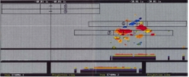
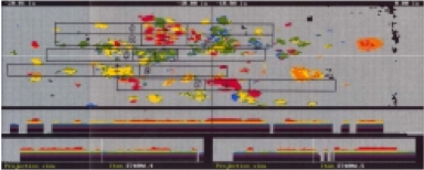
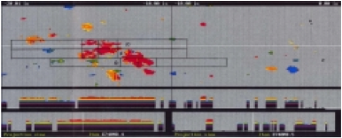
As shown in the figures, laminar crack indications appear at numerous locations and various depths. Many of the laminar cracks are closely spaced. Such laminar cracks can block angle-beam shear waves, making it difficult for conventional, shear-wave methods to detect and size through-wall- oriented cracks that may be hidden underneath the laminar cracks.


Comments and Discussion
There are no comments yet.
Add a Comment
Please log in or register to participate in comments and discussions.