| This article is part 2 of a 3-part series. |
| Part 1 | Part 2 | Part 3 |
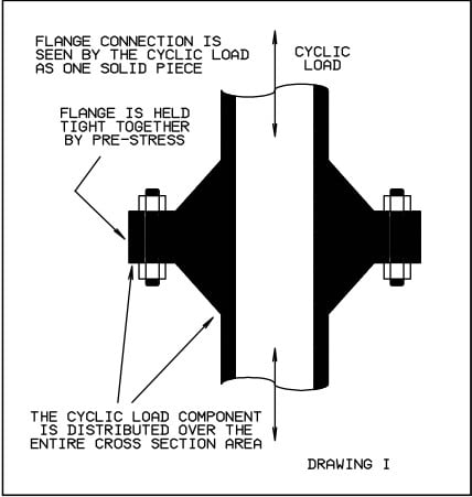
Continuing with the theme "a billiard ball on the end of a fly rod", this month we will look at one alternative to mounting a heavy block valve on a small diameter nipple in vibrating conditions. A popular situation is where the purpose of the branch is to feed process control metering, which is generally located some distance from the product flow line. A typical configuration is shown in Figure 1.
The block and bleed valve assembly is installed close to the branch connection of the flow line; in many cases, overhead where one must use a ladder to close in the instrument system for service. Moving the valve assembly away from the vibrating flow line, as suggested in Figure 2, provides two advantages. First, the heavy valves can be supported by the building, structure, while the vibration a longer, more flexible instrument line. Second, when instrument servicing or replacement is called for, it can be shut in from grade level without the operator having to climb up to the product flow line.
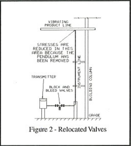
A disadvantage is that some plants use the first block valve for separation of maintenance responsibility. This change moves that demarcation farther from the flow line, adding some instrument tubing to operations maintenance. Historically, however, it has been a favorable trade off to avoid the unscheduled shutdowns and product releases resulting from cyclic weld failures.
In the next issue, we will look at a situation where the block and bleed valves cannot be moved down to the grade level.


Comments and Discussion
There are no comments yet.
Add a Comment
Please log in or register to participate in comments and discussions.