Introduction
Corrosion under insulation (CUI) is a real threat to the onstream reliability of many of today's plants. This type of corrosion can cause failures in areas that are not normally of a primary concern to an inspection program. The failures are often the result of localized corrosion and not general wasting over a large area. These failures can be catastrophic in nature, or at least, have adverse economic effect in terms of downtime and repairs. The American Petroleum Institute code, API 570, Inspection, Repair, Alteration, and Rerating of In-Service Piping Systems, the piping code first published in June 1993, identifies CUI as a special concern. Typically, as happened with API 653 and the Clean Water Act, the API codes become an industry standard, and the regulations demand that organizations maintain a program to meet that standard. OSHA 1910 is the rule with the teeth in this case.
CUI is difficult to find because of the insulation cover that masks the corrosion problem until it is too late. It is expensive to remove the insulation, particularly if asbestos is involved. There are a number of methods used today to inspect for corrosion under insulation. The main ones are profile radiography, ultrasonic spot readings, and insulation removal. The other method now available is real-time X-ray. Real-time x-ray has proven to be a safe, fast, and effective method for inspecting pipe in plant operations.
When Does Corrosion Under Insulation Occur?
The problem occurs in carbon steels and 300 series stainless steels. On the carbon steels, it manifests as generalized or localized wall loss. With the stainless pipes, it is often pitting and corrosion induced stress corrosion cracking (CISCC). Though failure can occur in a broad band of temperatures, corrosion becomes a significant concern in steel at temperatures between 32 F (0 C) and 300 F (149 C). Corrosion under insulation is caused by the ingress of water into the insulation, which traps the water like a sponge in contact with the metal surface. The water can come from rain water, leakage, deluge system water, wash water, or swearing from temperature cycling or low-temperature operation such as refrigeration units.
Systems Susceptible to CUI
API 570 specifies to the following areas as susceptible to CUI:
- Areas exposed to mist overspray from cooling water towers.
- Areas exposed to steam vents
- Areas exposed to deluge systems.
- Areas subject to process spills, ingress of moisture, or acid vapors.
- Carbon steel piping systems, including those insulated for personnel protection operating between 25 F and 250 F. CUI is particularly aggressive where operating temperatures cause frequent condensation and re-evaporation of atmospheric moisture.
- Carbon steel piping systems that normally operate in-service above 250 F (120 C) but are in intermittent service.
- Deadlegs and attachments that protrude from insulated piping and operate at a temperature different than the active line.
- Austenitic stainless steel piping systems that operate between 150 F and 400 F (60 C and 204 C). These systems are susceptible to chloride stress corrosion cracking.
- Vibrating piping systems that have a tendency to inflict damage to insulation jacketing providing a path for water ingress.
- Steam traced piping systems that may experience tracing leaks, especially at the tubing fittings beneath the insulation
- Piping systems with deteriorated coatings and/or wrappings.
- Locations were insulation plugs have been removed to permit thickness measurements on insulated piping should receive particular attention
All equipment will be shut down at some time or other. The length of time and the frequency of the downtime spent at ambient temperature may well contribute to the amount of corrosion under insulation that occurs in the equipment. It would be a daunting task to muster the resources needed to tackle this extensive list of piping with the traditional inspection methods. This is where real-time X-ray offers a real advantage. Once the damaged areas are identified, follow-up X-rays and ultrasonics can measure the loss by external corrosion. These techniques will not detect CISCC in stainless steels.
Alternative Inspection Methods
The present corrosion under insulation detection methods are:
Profile Radiography
Exposures are made of a small section of the pipe wall. A comparator block such as a Ricki T is used to calculate the remaining wall thickness of the pipe. The exposure source is usually Iridium 192, with Cobalt 60 used for the pipes of the heavier wall. (See Figure 1).
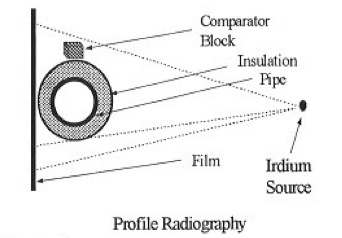
Profile radiography is an effective evaluation method, but becomes technically challenging in piping systems over 10 inches (25.4 cm) in diameter and only offers the limited luxury of verifying relatively small areas. This technique will not detect CISCC in stainless steels. In addition, radiation safety can be a real concern. Nobody can work within the area while the inspection is under way, this can result in downtime and manpower scheduling conflicts.
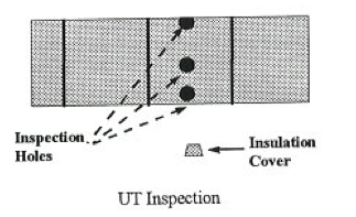
Ultrasonic Thickness Measurement
This is an effective method, but limited to a small area (Figure 2). It is expensive to cut the insulation holes and cover the holes with caps or covers. It is not practical to cut enough holes to get a reliable result. The inspection holes cut in the insulation may compromise the integrity of the insulation and add to the corrosion under insulation problem, if they are not recovered carefully. This technique will not detect CISCC in stainless steels.
Insulation Removal
The most effective method is to remove the insulation, check the surface condition of the pipe, and replace the insulation. This approach will detect CISCC in stainless steels; may require eddy current or liquid dye penetrant inspection. This is also the most expensive method in terms of cost and time lost. The logistics on insulation removal will probably involve asbestos and its attendant complications. Process related problems may occur, if the insulation is removed while the piping is in service.
Infrared
In the right conditions, infrared can be used to detect damp spots in the insulation, because there is usually a detectable temperature difference between the dry insulation and the wet insulation. Corrosion is a distinct possibility in the areas beneath the wet insulation.
Neutron Backscatter
This system is designed to detect wet insulation in pipes and vessels. A radioactive source emits high energy neutrons into the insulation. If there is moisture in the insulation the hydrogen nuclei attenuate the energy of the neutrons. The instrument's gauge detector is only sensitive to low energy neutrons. The count displayed to the inspector is proportional to the amount of water in the insulation. Low counts per time period indicate low moisture presence.
Real-Time Radiography
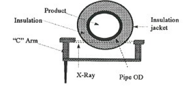
Fluoroscopy provides a clear view of the pipes outside diameter through the insulation, producing a silhouette of the pipe outside diameter (OD) on a TV-type monitor that is viewed during the inspection. No film is used or developed. The real-time device has a source and image intensifier/detector connected to a C-arm (see Figure 3). There are two major categories of RTR devices on the market today; one using an X-ray source and one using a radioactive source. Each has its own advantages and disadvantages, however, the X-ray systems deliver far better resolution than the isotope type equipment.
The X-ray digital fluoroscopy equipment operates at a maximum of 75 KV, a low-level radiation source, but the voltage is adjustable to obtain the clearest image. This allows for safe operation without disruption in operating units or even confined spaces. The radiation does not penetrate the pipe wall as more powerful gamma-ray or x-ray would, instead it penetrates the insulation and images the profile of the pipe's outside wall. The radiation is generated electrically so the instrument is perfectly safe when the power is off, whereas the Iridium 192 used in wall shots produces gamma-radiation constantly, even when shielded within the camera. Therefore, the gamma-ray camera always needs careful supervision and control during all operations, including transportation and shipping. The systems with the electrically generated X-rays are far more convenient for shipping.
The new systems come with a heads-up, video display. The helmet-mounted, visor-type video-display frees the system operator's hands so that he can maneuver the C-arm while keeping the image before the operator at all times. The heads-up display also improves interpretation by shielding the screen from the sun. The video images can be printed on site using a video printer or recorded using a standard VCR for evaluation later.
Performing the Inspection
Using the sorting criteria listed above it is possible to prioritize a list of piping for inspection that is manageable in a reasonable time frame. The CUI inspection crew then inspects the pipes iso by iso.
The "C" shaped arm is the actual device used to scan the pipe. A cathode ray tube on one side generates the x-rays, shooting them across to the receiver on the other side. The operator manipulates the arm around the pipe, guiding it by the black and white heads-up display on his hard-hat. A typical scan will go up the pipe while moving the arm about 45 degrees to both sides of the track. The C-arm is then rotated 180 degrees and the pipe is scanned downward in a similar fashion. After rotating 90 degrees the up and down process is repeated.
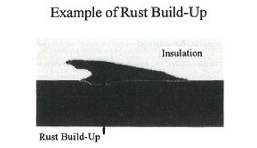
Results
To the untrained eye, the image on the screen would appear to indicate very serious corrosion. However, what is being imaged is the exfoliation of the rust (See Figures 4 and 5.) Performing the inspection in this manner the inspector can inspect a considerable amount of pipe in a short time.
Limitations
One of the main limitations of the system is the C-arm. There are a couple of sizes of C-arms available. The manufacturer has had success in checking pipes up to 24 inches in diameter. These systems were not originally designed for the field but rather for laboratory work. This limitation has been addressed and the systems available today are more robust. However, they still require a lot of care and attention. There will always be some percentage of piping where real-time X-ray can not be used. The prime example is the center lines among tightly nested pipelines with little clearance between the pipes. Finally, while the X-rays are low energy, they are still radiation, and so the system must be used with extreme caution.
Real Time Radiography Uses to Locate Piping Components for Positive Materials Identification Programs
Alan Wolf of Exxon Research and Engineering Company recently wrote, "Over the years the industry has experienced several incident failures where the root cause was attributed to the installation of improper material." He also suggests real-time X-ray as an effective alternative to insulation removal in the search for piping components. Using correct procedures with real-time radiography extensive field tests have demonstrated a 99% field reliability of detecting circumferential welds with a weld crown of at least 1/32 to 1/16 inch (1-2 mm). Figure 6 shows an RTR image of a weld crown through insulation. RTR's proven ability to detect weld crowns offers compelling testimony of the system's ability to detect CUI.
References
- Kobrin, G. and Moniz B. Inspection, maintenance and prevention of corrosion of piping and equipment under thermal insulation. First International Symposium on Process Industry Piping, December 14-17, 1993, Orlando, Florida, Sponsored by NACE International and MTI.
- Kohl, R. and Dougan, K. Methodology for detecting corrosion under insulation. Paper given
- Wolf, H.A. (1995) Positive materials identification of existing equipment. Second International Symposium on Mechanical Integrity of Process Piping. MTI Publication No. 48.


Comments and Discussion
Add a Comment
Please log in or register to participate in comments and discussions.