I decided I should quit picking on deficient management styles and get back to some technical topics. Everyone likes a good rant, but that has its limits. Although I won’t stop for good (ranting, I mean…).
Fatigue is interesting to me as a failure mechanism for many reasons. First off, it accounts for roughly 80% of all industrial failures. Think about that for a second. Think about the fatigue failures you have seen in your career.
It is also interesting because it can be difficult to detect, in some situations, before it goes through wall. It’s one of the mechanisms that can quickly go catastrophic, ignoring the design principle we all love -- "leak before failure.”
Some of the more interesting failures in history were fatigue-driven, but more on those in a bit.
Now, let’s go assess for fatigue. Crack open API RP 571. There is a section on thermal fatigue. Not too helpful for other fatigue mechanisms, but understandable as it is not a specific damage mechanism to the petrochemical industry.
Read Related Articles
Maybe RBI will help. Nope – fatigue specifically is not effectively covered under that assessment system.
So, a significant source of failures is not covered in an effective way by many of the tools we use day to day. Is it a problem that we seem to have a lack of information? For new personnel, definitely. I see fatigue failure solutions stump a lot of people and organizations.
In fact, I would say fatigue and creep are at the top of the list of poorly understood failure mechanisms in the integrity world. Maybe an article on creep is in order as well.
What is fatigue?
The textbook definition is as follows:
"Fatigue is where a material cracks or fails due to repeated cyclic loading, quite often at stresses below the UTS (Ultimate Tensile Strength) or even the yield strength of the material. For fatigue failures to take place, the cyclic stress must have a tensile component.
The cyclic stress level that a material fails at is known as the fatigue strength. The higher the stress level (i.e., the closer to the ultimate tensile strength of the material) the fewer number of cycles will be required to cause the material to fail.
Under given loading and surface (stress riser) conditions, fatigue life can be established through fatigue testing. Fatigue testing plots the number of cycles to failure at given stress levels (S/N Diagram – Stress/Number of Cycles).”
That’s all well and good, but it doesn’t really help an inspector, or someone trying to plan an inspection for potential or known fatigue issues. There are a few more things we should take a look at.
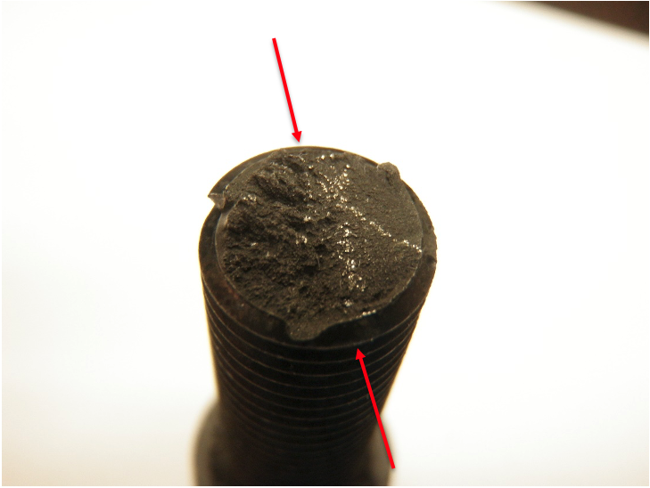
Fatigue failures usually initiate in a highly stressed region on the surface of a component. The crack propagates under the applied stress through the material until a fracture occurs. Fatigue failures are progressive fractures that often show characteristic beach marks (clamshell or arrest marks). The beach marks are centered around a common point that corresponds to the fatigue crack origin. Multiple points of origin, say along a change in OD on a shaft or along the toe of a weld with a high final cap due to poor welding practices, result in a variation of these marks known as “ratchet marks.”
Beach marks can be thought of as the start/stop positions of the progressing crack as it goes through the cyclic loading. Each cycle takes the crack a step through the material until the remaining material isn’t enough to hold the load on the part and a sudden fast failure occurs. The individual steps are generally too small to see, but the larger arrest points make these characteristic beach mark fracture surfaces.
Fracture (beach mark) appearance varies depending on the stress level, type of stress, shape of part, and the degree of stress concentration. An example of a failed bolt off of an instrumentation fitting is shown below:
Since fatigue failures usually initiate at the surface of a section at stress concentrators, any factors which change the surface will have a large effect on fatigue strength.
Some examples of surface changes include:
- Stress concentration due to changes in shape, keyways, threads, poor weld profiles at the root or toe of the cap, etc.
- Surface roughness, such as scratches. A polished surface has a higher fatigue strength than a roughly machined surface.
- Metallurgical inclusions which interrupt the surface continuity (i.e., the flakes of graphite in grey cast iron)
- Residual stress patterns. Introducing residual compressive stresses (i.e., shot peening, carburizing, induction, or flame hardening) improves fatigue resistance by putting the surface into compression (reducing or eliminating the tensile stress at the surface).
- Atmosphere – introducing a corrosive environment can cause surface changes in a cyclically stressed part. These surface changes act as stress concentrations which greatly accelerate failure. Materials that exhibit definite endurance limits if tested in air change the shape of their S-N (Strength vs. Number of Cycles to Failure) diagram when tested in a corrosive media. Think about the effect a chloride stress corrosion crack would have on a stress riser.
Obviously, as an inspector, you want to inspect where fatigue is most likely to start. Applying surface inspection techniques to any of the above high-risk locations and scenarios is a good starting point when known cyclic loading exists.
Let’s look at a few different fatigue failures I have seen in my career to get engaged on what all is captured by this seemingly innocent word:
Case #1: Pipeline failure
I started my career doing failure analysis through a consulting firm, predominantly on behalf of insurance companies. An early job involved a fatigue failure of a sour gas pipeline. The pipeline ran from gas fields through some pretty remote terrain and, at one point, went under an ecologically sensitive river. They had, a few years before, twinned the line under the river and put in valving and instrumentation so that if a leak developed in one of the twinned lines under the riverbed, it would close in that section. The lines were buried under the riverbed; not sure how deep originally, but it became a moot point.
A small dam had collapsed upriver due to an abnormally high amount of snow, followed by heavy rain as the snow melted. This caused a massive surge of water down the river that washed out the riverbed and exposed this twinned pipeline. These lines were now free hanging and swaying in the current. There is your cyclic loading.
The upstream line had a welding defect, specifically a heavy arc strike that caused a physical divot in the OD wall of the pipe. The cyclic loading and this stress concentrator caused a fatigue crack to form and eventually caused the upstream line to fail by cracking in half.
The instrumentation picked up the pressure drop on that section of line and shut it in, putting all flow to the downstream line. The operators saw this and made a note to get out in the next day or so to check what was going on.
Unfortunately – and this is why insurance companies were involved – the two halves of the failed upstream pipe drifted into the downstream pipe and caused it to fail as well. The designers of the fail-safe had not anticipated leaks in both sections of the line at once, so the valving did not shut in the twinned section when it started leaking into the river.
I guess this story is also a good argument for why quality control is important, as no arc strike may have meant no stress risers and higher fatigue strength.
Case #2: Small bore connections to larger lines
I have seen more small diameter fitting failures due to fatigue than I care to think about. The biggest problem areas are generally around running pumps whose vibration is transferred into the attached piping.
One that has stuck with me was instrumentation tubing coming off a weldolet to a 10-inch process line. The tubing was always vibrating due to the proximity of a pump. A failure occurred on the tubing connection, where the tubing was scored by the compression fitting. The response was to make the tubing connection bulletproof through clamp-on stiffeners, which had the effect of moving the fatigue crack from the weldolet to the pipe weld.
Case #3: Process flow considerations
Process flashing (i.e., through the pressure drop of a control valve) can cause vibrations. There was a situation in a hydrotreater where the original process design called for the product to flash into a section of a fractionation tower. However, piping changes and the addition of instrumentation orifice flanges moved the flashing back into the 8-inch line flowing into the fractionator.
This change started causing the line to move excessively. At its worst, I recorded 3 inches of vertical movement on the upstream spring hanger. This caused a small-bore drain connection to fail. The maintenance solution was to make this small-bore connection rigid as hell by welding in gussets. This did extend the fatigue life slightly, but then the gussets failed at the welds, and then the small-bore connection failed again.
What fixed this was redesigning the piping to put the flashing back in the tower as per the original unit design and take away the source of the vibration.
Case #4: Thermal cycling
My favorite example of extreme thermal cyclic loading comes from a delayed coker unit. When switching drums, quench water was added to cool the drum about to be emptied through the drum feed line. The procedure said to wait until it had cooled some, but because time is money, this wasn’t followed. Ambient-temperature water would be dumped into the feed line running up the side of the coker while it was still almost at full operating temperature.
When this flashed to steam, it would cause the line to jump 3 to 6 feet. That’s right – feet! As you can imagine, fatigue failures were common wherever the line was fixed and at certain welded joints.
Bonus Case: De Havilland DH106 Comet
As well as my personal examples above, some famous failure cases are responsible for our current understanding of fatigue. I want to take a quick look at one you may not have heard of but that drastically changed our understanding of fatigue and how aircraft are designed and tested.
The De Havilland DH106 Comet was the world’s first production commercial jet airliner and went into service in 1952. It featured Ghost turbojet engines buried in the wing roots, a pressurized cabin, and large square windows. Anyone else thinking stress risers yet?
Within a year of the Comet entering service, problems started to emerge. Three Comet airplanes crashed in 12 months in highly publicized accidents after seemingly breaking apart in flight. Two of these crashes were found to be due to metal fatigue, a mechanism that was not well understood at the time. De Havilland withdrew the Comets from service and did some extensive full-scale loading testing that included things like flexing the wings and putting the cabin through pressure cycles. Skin rivet issues existed, but what they soon found was that the real issues were the stress risers created at squared-off windows and other openings. They made the changes to eliminate these issues, as well as set up inspection intervals for areas identified as risky by the full-scale cyclic loading testing.
De Havilland never recovered its civilian market share (no one trusted them anymore, even with the changes) after these crashes, but Boeing and other competitors paid attention and made changes to their designs before putting them into production. This accident is also what led to the requirement that all new plane designs need to go through full-scale fatigue testing as part of getting approval.
As an aside, military versions of the “new and improved” Comet flew until 1997 without significant incident.
How do we fix fatigue? Well, the favorite answer I get from mechanical engineers is to add stiffeners, and make it more rigid! Does that work? Seldom. Most of the time, not at all. It either moves the failure to another location in the assembly or may buy a little more time in terms of the stiffener will fail first. From what I have seen, not addressing or isolating the root cause of the vibrations tends to be only a temporary fix.
Finite element analysis (FEA) and fatigue life assessments can help, when applied properly, with all data, by engineers/consulting firms that know what they are doing. When done correctly, it is also a big help for the inspector in identifying where fatigue cracking is most likely to start and how many cycles it will likely take to fail. Combine that information into an inspection plan, and you know when to apply an inspection and at what location. It can also help with an actual fix by re-engineering the system if it is cost-effective.
Remember, when you get fatigued, you can fall down. When the process pipe gets fatigued, it can blow up.


Comments and Discussion
There are no comments yet.
Add a Comment
Please log in or register to participate in comments and discussions.