Introduction
Of the nearly 70 damage mechanisms listed in the latest edition of API RP 571, do you know which ones may embody the highest FEMI risk at your operating site? I would venture to say it might very well be the ones that are highly localized in nature and, therefore, the hardest to find without an excellent understanding of the threat, effective inspection procedures, detailed inspection planning, and knowledgeable personnel guiding the effort to find localized damage mechanisms (DMs) and corrosion [1]. In this article, I will use localized DMs and localized corrosion interchangeably to refer to a wide variety of localized DMs in API RP 571 [7].
Over the last 54 years of my experience in the petrochemical and refining industry, I have been involved in and/or read about a lot of major FEMI failure investigations, including numerous ones that involved large losses of primary containment (LOPC). Many of them involved damage mechanisms that can be highly localized and difficult to find such as those identified in a previous article [5]. I clearly remember several incidents off the top of my head:
- One is where the inspector knew that the damage he was looking for might be highly localized, so he was taking spot ultrasonic thickness testing (UTT) on a grid pattern every 12 inches on a high pressure/high temperature hydro-process line. Unfortunately, he missed the highly localized corrosion that occurred at a Tee fitting between two of his closely spaced condition monitoring locations (CMLs). The line blew out and released thousands of pounds of hot light hydrocarbon in a few seconds before the vapor cloud found an ignition source and caused a $100M fire.
- Another one that I remember well is where an inspector knew he might be looking for a local thin spot on the back of an elbow due to potential corrosion-erosion. So, he took 12 UTT measurements on the 8-inch elbow but missed the localized corrosion because of the peculiar pattern of corrosion-erosion. The elbow blew out and left a large hole through which you could easily pass a football. That failure released 30,000 lbs of light hydrocarbon in 30 seconds and caused $700M in destruction when the vapor cloud found an ignition source.
- Another case involved a line in a piperack where localized corrosion does not usually occur, so CMLs were simply scattered down the line as the inspector saw fit to monitor what he thought would be general corrosion. He was unaware that localized corrosion could even occur in the line because the line was in a piperack and not covered by the process unit corrosion control document (CCD) where the process fluid originated. But, lo and behold, precipitation of a corrosive, wet contaminant occurred in the middle of an uninsulated straight pipe section and eventually blew out a large hole with a very loud bang. Fortunately, in this case, the light hydrocarbon did not find an ignition source and floated harmlessly away. Plant personnel knew they had dodged a bullet (more like a hypersonic missile) and the result was not too much more than the large deposit in the inspector’s shorts.
The total costs involved in big LOPC events can be largely due to lost production in certain market conditions which can sometimes dwarf the costs of repair from an LOPC event. If serious or fatal injuries resulted from the event, the impact can be overwhelming and even threaten the site’s desire to continue in business (which happened recently on the east coast of the US). I could provide several more examples of big events caused by localized corrosion LOPCs, but I’m sure you get the point. Undetected localized corrosion is a high priority FEMI threat [5].
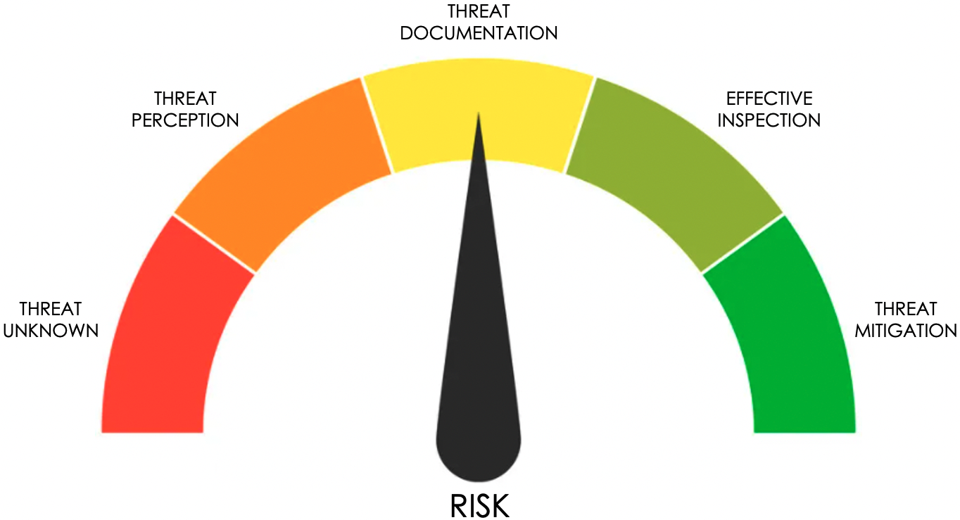
The risk meter shown in Figure 1 shows the primary stages of risk associated with localized corrosion in a process unit.
- Sites in the red sector of the risk meter will have the highest risk due to their relative ignorance of the threat of LOPC (e.g., potential for rupture) from localized corrosion.
- In the orange sector of the risk meter, the site is beginning to become aware of and understand the potential threat of major LOPC from localized corrosion.
- In the yellow sector, the site is conducting a damage mechanism review (DMR) and documenting it in a good quality CCD focused on the potential for localized corrosion.
- In the lighter green sector, the site is planning and conducting the effective inspections to find and map out the threat of all localized corrosion DMs.
- And in the darker green sector, the site is implementing the appropriate risk reductions to control and/or reduce the threat of LOPC from localized corrosion.
Hopefully, your site is moving the needle toward or into the green sectors.
What Damage Mechanisms and Process Conditions Most Commonly Cause Localized Corrosion?
In the orange sector of our risk meter shown in Figure 1, the site begins to perceive the threat of localized DMs and starts to be concerned about the potential for FEMI events (possible piping rupture from LOPC) caused by localized DMs. Activity may include doing more frequent inspections with effective nondestructive examination (NDE) techniques and adding some CMLs at locations of concern so they may focus more attention on those areas. API RP 571 provides a lot of informative guidance on the types of DMs as well as the process conditions that cause localized DMs [7]. Some of those DMs that I have encountered (in no particular order) most often include:
- Local areas of corrosion-erosion and flow accelerated corrosion (FAC)
- Points where knowledgeable process/corrosion engineers may expect precipitation of wet corrosive contaminants (solids/liquids) to occur
- Ammonium bisulfide (hydrosulfide) containing streams
- Wet ammonium chloride containing streams
- Downstream of flow disrupters in piping systems, like orifice plates, control valves, excess weld root profiles, Tee junctions, etc.
- Places where corrosive condensate hits its dew point in wet gas streams (especially in overhead piping, near exchanger bundles or inside air cooler tubes)
- Places where by-pass piping reconnects with the main process flow (mix points) [1]
- Places where there is normally no flow (deadlegs) [1]
- Points where normally closed valves (NCV) are leaking through (just a little)
- Places where turbulent fluid dynamics cause circular eddy flow patterns
- Places where low silicon carbon steel piping is installed in hot sulfidic fluids [8]
- Places where carbon steel piping with high residual elements is installed in some HF services [9]
- Naphthenic and other organic acids under certain process conditions
- Services that can result in concentration cells (e.g., under-deposit attack) or crevice corrosion
- High temperature hydrogen attack (HTHA) service conditions, especially in non-PWHT’d carbon steel heat affected zones, but may include random spots in base metal in the hotter regions of exchangers (a whole ‘nother story for another time)
And a few more as indicated throughout API RP 571 [7].
How Do You Know if You May Be Susceptible to Localized Corrosion?
The answer to that question is fairly straight forward, but still not fully entrenched at all sites. It begins in the yellow sector of Figure 1 and involves having knowledgeable individuals document what credible damage mechanisms are likely to occur in each individual process unit and where they are likely to occur [1]. As you undoubtedly know, doing a damage mechanism review for each process unit is a requirement in our industry piping and pressure vessel codes (API 570/510) as the basis of inspection planning – and NOT just part of RBI preparation. It’s a requirement for all types of inspection planning. Of course, DMRs have to be conducted by knowledgeable corrosion and process specialists who know and understand the chemistry and materials of construction in the process unit involved and the potential damage mechanisms that may occur. It’s NOT just a matter of having any inspector or engineer sit down, page though API RP 571, and conduct a DMR. I’ve seen the results of that type of DMR, which might have had more value if they had been documented on toilet paper.
Even when knowledgeable corrosion specialists are involved in the DMR, far too often they are not involved in the necessary follow-up process of helping to designate where the CMLs should be placed for the best chances of finding localized DMs. Likewise, knowledgeable NDE specialists need to be involved to determine what type of NDE techniques may be needed to find and size the localized damage, including screening techniques as well as those that can quantify and characterize the damage. Surely not every site has those knowledgeable corrosion and NDE specialists, but sometimes they are available elsewhere within the company or from a few capable engineering service contractors [1].
How Should you Document the Potential for Localized Corrosion?
Having completed the DMR, the site would have moved well up into the yellow sector of the risk meter for LOPC from localized corrosion. There are a few different ways to document the DMR, but the best way I know of is to follow the excellent guidance contained in API RP 970 on Corrosion Control Documents, including all the suggested details in that standard on what constitutes the best type of CCD [1, 6]. So, if you have a high quality DMR/CCD type document for each of your process units, you will have a very good basis for knowing:
- If your process units may be susceptible to highly localized corrosion (or other localized damage mechanisms).
- Which specific damage mechanisms are of concern.
- Under what process conditions they are likely to occur.
- Where they are most likely to occur in individual process units.
- What type of equipment may be exposed to localized DMs.
- How to find the damage.
After you have an excellent documented DMR/CCD, then comes the part where the “rubber meets the road” – planning and applying the right NDE techniques in the right locations at the right frequency in each process unit. That occurs in the light green sector of our risk meter in Figure 1.
How Do You Find and Quantify Localized Corrosion?
Having completed an effective DMR and recorded it in the CCD, the site is ready to move into the light green sector on the risk meter in Figure 1 where effective inspections are planned and conducted to find localized corrosion damage. Finding an insidious, localized damage mechanism can be difficult without the right NDE knowledge and the right NDE techniques and procedures.
Most Inspectioneering Journal readers know well that spot UTT for finding localized corrosion is about as useful as looking for a needle in a haystack without a metal detector or using hammer testing to find thin spots, which is a technique that was still in use when I started work in the industry back in 1968. Times have changed, thank goodness. There are now a variety of NDE techniques that can be used to find localized corrosion. If you haven’t yet reviewed the third edition of API RP 571 published in March 2020, you will note that it has been substantially updated and improved by a combination of efforts by numerous corrosion and inspection specialists from the API Subcommittees on Corrosion and Materials (SCCM) and Inspection and Mechanical Integrity (SCIMI) [7]. One of the most significant improvements in API RP 571 is the inclusion of much more useful information in the seventh section of each individual article that now provides much better guidance on what NDE techniques are better suited to detect each different type of damage mechanism. The NDE guidance in API RP 571 for localized corrosion detection, sizing and characterization can be supplemented by consultation with NDE specialists who should be up to date on the pros/cons of the various NDE techniques that can be applied to find localized corrosion in each specific circumstance [1].
Typical examples of NDE techniques for localized corrosion include:
- Guided wave testing (GWT) for screening piping systems
- A wide variety of UT scanning techniques (manual and automated)
- Radiographic testing (RT) including profile and density-contrasting techniques
- Internal rotating inspection system (IRIS), magnetic flux leakage (MFL), eddy current testing (ECT), near-field testing (NFT) for exchanger and air cooler tubes
- Strategically located, permanently mounted sensors
Reducing your Risk of LOPC from Localized Corrosion
If you have conducted effective inspections for localized corrosion and found nothing, and you have not had any near-misses or leaks from localized corrosion, then you may already have the appropriate threat mitigations in place; therefore, you may already be in the darker green sector of the risk meter in Figure 1. On the other hand, if you found localized corrosion or have previously experienced leaks due to localized DMs, you may need some more risk mitigation actions in order to reduce your risk of LOPC. If you have experienced some LOPCs from localized corrosion despite your efforts to find it, then you may need to implement the PERI Model to improve your inspection planning to find the threat before it finds you again [3].
So, what are your other options once you know that you are exposed to a level of risk for FEMI events due to localized corrosion that may be higher than you and/or your site management are willing to tolerate? If your site’s PHA/HAZOP analysis concludes that all the FEMI risk control and reduction methods and techniques currently in place are not sufficient to stay within your site’s risk tolerance for a FEMI event caused by undetected localized corrosion, then your site still may have a few more options to consider for risk reduction to move farther into the darker green sector on the risk meter in Figure 1 [4]. Those options may include:
- Changes in process conditions to avoid whatever may be causing localized corrosion. This effort clearly takes a detailed analysis with process engineering expertise to determine what changes are practical and economically feasible using appropriate MOC procedures. Can you institute process changes such as:
- Improved water wash systems?
- Changes in fluid flow dynamics or temperature profiles?
- Elimination of deadlegs?
- Improved design of mix points and other areas that create flow turbulence?
- Reduction in process contaminants that may give rise to localized corrosion?
- Changes in temperature schemes to move dew points or precipitation points into areas with more corrosion resistant materials of construction?
- Changes in materials of construction. Over the past few years, I have been encouraged by the number of companies/operating sites willing to make the investment to “alloy up” their equipment and piping as opposed to relying on the inspection program to “keep them out of trouble.”
- Implement layers of protection risk review [5]. This can help us determine if we have sufficient, effective layers of protection in place, such as safeguards, protective barriers, design reviews, administrative controls, IOWs, operating practices, and/or more rigorous MOC focused on potential FEMI threats.
With the implementation of appropriate risk mitigations for the threat of LOPC from localized corrosion, the site has entered solidly into the darker green sector of the risk meter. But, in order to stay there, the site will need ongoing inspections and process and control systems (including IOWs) to make sure their operations stay within the appropriate boundaries to avoid unanticipated localized corrosion.
Summary Comments
This article has been about another one of those potentially high-risk FEMI threats that need to be identified and controlled by implementing the Big Five Risk Management Programs [2]. The petroleum industry has come a long way in reducing the likelihood of large LOPC events by the many risk management techniques put in place by PSM and FEMI groups at many companies and operating sites over the last couple of decades. But we still can and should make improvements where needed. As I think back about the biggest FEMI LOPC events that have happened since the turn of the century, I’m concerned that the threat of undetected localized corrosion (or other localized damage mechanisms) still needs more attention for risk reduction.
Questions for you to Ponder with Regard to the Localized Corrosion Threat
- Do you know where your site currently stands on the risks of LOPC (e.g., rupture) from localized corrosion/DMs on the risk meter in Figure 1?
- Do you know what your FEMI risks (probability and consequences) are associated with undetected localized corrosion/DMs?
- Are your DMRs and CCDs as good as they need to be to provide guidance on your susceptibility to localized corrosion/DMs and what to do about it?
- Are you using the most appropriate NDE techniques to find, size, and characterize localized corrosion/DMs?
- Do you need to seek outside expert advice from corrosion/materials and/or NDE specialists if they are not available at your site?
- What is your residual risk once you have implemented the best FEMI inspection and mitigation program for localize corrosion/DMs and what are your other options if that risk is still more than your site is willing to tolerate?
- Can your site afford not to be in the darker green sector on the risk meter in Figure 1?
References
- Reynolds, J., 2015, 101 Essential Elements in a Pressure Equipment Integrity Management Program, Second Edition, Inspectioneering, Spring, TX, Chap. 3, 5, 11,12,15, 52, 85.
- Reynolds, J., 2021, “How Effective Are Your Big Five Risk Management Programs?”, Inspectioneering Journal, 27(1), pp. 25-33.
- Reynolds, J., 2021, “Applying the PERI Model to Fixed Equipment Mechanical Integrity,” Inspectioneering Journal, 27(5), pp. 15-18.
- Reynolds, J., 2013, “Managing the Risks Associated with Fixed Equipment Mechanical Integrity Issues,” Inspectioneering Journal, 19(3), pp. 8-11.
- Reynolds, J., 2021, “How to Reduce Your Exposure to High Consequence FEMI Events”, Inspectioneering Journal, 27(3), pp. 19-23.
- API RP 970, 2017, Corrosion Control Documents, First Edition, American Petroleum Industry, Washington, DC.
- API RP 571, 2020, Damage Mechanisms Affecting Fixed Equipment in the Refining Industry, Third Edition, American Petroleum Industry, Washington, DC.
- API RP 939C, 2019, Guidelines for the Avoiding Sulfidation (Sulfidic) Corrosion Failures in Oil Refineries, Second Edition, American Petroleum Industry, Washington, DC.
- API RP 751, 2021, Safe Operation of Hydrofluoric Acid Alkylation Units, Fifth Edition, American Petroleum Industry, Washington, DC.


Comments and Discussion
Add a Comment
Please log in or register to participate in comments and discussions.