Introduction
Remaining life assessment (RLA) of complex assets, including fixed equipment, piping, rotary, and packaged sub-assets, has always been challenging for integrity engineers. There is no exclusive standard or recommended practice available that discusses a specific methodology that can systematically and consistently be used for estimating remaining life of complex assets. An example of a complex asset is a feed filter package in a refinery DHDT unit. Such complex assets need to be broken down into sub-assets such as fixed equipment, piping, and rotating equipment for individual assessments as per applicable in-service inspection codes. Well stimulation service (WSS) units are complex in a similar way, and this article covers generic RLA methodology for WSS units.
Well Stimulation Service Units
The purpose of WSS units is to assist operator companies in well stimulation jobs. This can be achieved by increasing well productivity using fracturing, acidizing, and water control treatments. Depending on the oil field, WSS units can be truck-mounted (mobile) or stationary.
The most common types of WSS units are as follows:
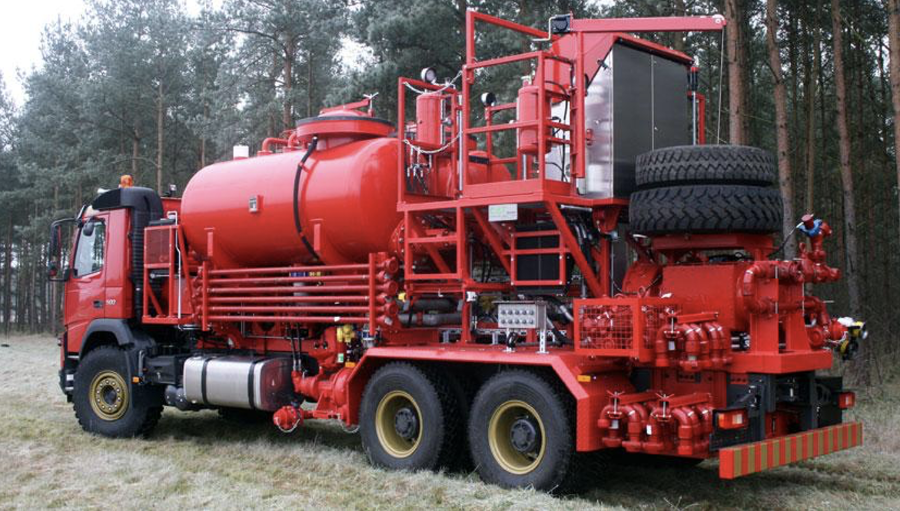
- Acid pumping unit (see Figure 1)
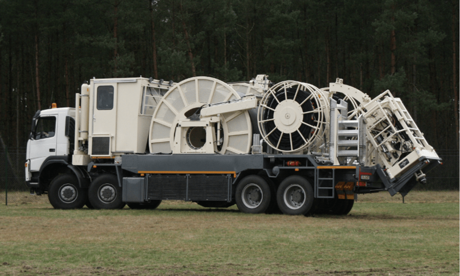
- Coil tubing unit (see Figure 2)
- Blender unit
- Nitrogen pumping unit
- Fluid pumping unit
- Hot oil circulation unit
- Data acquisition and transmission van
- Multi-purpose pumping unit
Each of the above WSS units is meant for a specific well stimulation job. For example, the acid pumping unit pumps the acid into the wellbore to remove near-well formation damage and other damaging substances. This procedure commonly enhances production by increasing the effective well radius. The coiled tubing unit’s coil is injected into the existing production string, unwound from the reel, and inserted into the well. The coil is then retracted back to the reel drum using an injector head to complete the coil tubing operation.
Challenges Faced to Perform Remaining Life Assessment on WSS Units
The variability in types of WSS units and their individual complexities require conceptualizing a methodology of conducting RLA that ensures optimum use of resources. The execution of such RLA methodology requires a streamlined approach where criticality of sub-assets, past breakdown and maintenance history, and future corporate requirements of operator companies coincide. The truck mounted WSS units will require a field integrity check and an in-house engineering assessment for traction components (chassis, suspensions, brakes, leaf springs, etc.) as well.
To illustrate sub-assets, the following WSS units are broken down into two major components: acid pumping unit (APU) and coil tubing unit (CTU).
The acid pumping unit component includes:
- APU tanks and APU piping
- Triplex pumps
- Centrifugal charge pump, hydraulic and pneumatic system
- Loading gear (Bowie) pump
- Carrier engine
- Traction components (chassis, suspensions, leaf springs, brakes)
- Exhaust system
The coil tubing unit component includes:
- Injector head
- Reel assembly
- Hydraulic system
- Crane assembly
- Blow-out preventer
- Carrier engine
- Traction components (chassis, suspensions, leaf springs, brakes)
- Exhaust system
It would be evident to an RLA engineer that no singular procedure or technique is sufficient to assess the WSS unit. Therefore, it is imperative to break down the WSS unit into major components (sub-assets) and assess each sub-asset using a singular methodology. Subsequently, a holistic approach can be adopted to analyze the WSS unit’s condition as a complete unit and suggest repair, replacement, or salvage of certain sub-assets or the entire WSS unit. For example, the traction components might be completely damaged or near the end of life, but the mounted WSS unit might have longer remaining life left with the governing component being in good condition. The RLA engineer might, in this case, suggest that the WSS unit be continued with a new truck as its mount.
Methodology to assess remaining life of WSS units
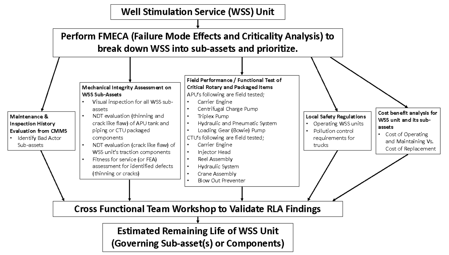
A generic methodology to assess remaining life of WSS units can be done in the following major steps:
- Prioritize and break down WSS into sub-assets by FMECA, if not already done by the operator
- Maintenance history evaluation from the computerized maintenance management system (CMMS), identify bad actor sub-assets; a site interview with the WSS operations team is important
- Mechanical integrity assessment on static equipment, piping, and other WSS sub-assets, including:
- Visual inspection for all WSS sub-assets
- NDT evaluation (thinning and crack-like flaw) of APU tank and piping
- NDT evaluation (crack-like flaw) of WSS unit’s traction components
- Fitness for service assessment for identified defects (thinning or cracks)
- Field performance/functional test of critical rotary and packaged items per OEM (or site operations) recommendations
- Cost benefit analysis for WSS unit and its sub-assets (i.e., cost of operating and maintaining versus cost of replacement)
- Local safety regulations pertaining to operating WSS units or pollution control requirements for trucks mounted underneath
- Cross functional team workshop to discuss, evaluate, improve, and validate the remaining life assessment findings
The methodology will vary for each WSS unit to account for its uniqueness in construction and operation. Figure 3 depicts the flow chart of generic RLA methodology with examples of included APU and CTU WSS units.
Conclusion
The generic RLA methodology described in this article can be used to assess other types of truck mounted WSS units, with sub-assets being different. It is important for RLA engineers to develop templates (or formats) for various stages of this generic RLA methodology. These templates will help to evaluate WSS sub-assets consistently and present the results methodically, should there be many WSS units to be assessed as a corporate initiative.


Comments and Discussion
There are no comments yet.
Add a Comment
Please log in or register to participate in comments and discussions.