This post is based on three articles from the January/February, March/April, and May/June 2011 issues of Inspectioneering Journal by Del Underwood. You can find the original articles here, here, and here.
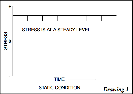
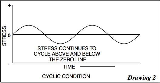
One problem that nearly everyone in the industry has experienced is where, in certain situaions, a tight bolt will perform correctly while a loose bolt will fail. This happens because of two fundamental types of loading that a bolt may encounter: “static” or steady state loading, and “cyclic” or continuously changing loading. Both of these conditions, plus a combination of both, are shown graphically in drawings 1, 2, and 3, which show that, at best, the cyclic strength range is about one-half.
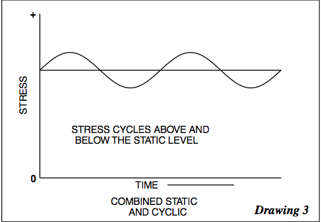
Of course, bolts involved in process equipment are rarely loaded in a completely static or cyclic condition. To give an example: the pretension or torque up of a bolt is a static component while loading is a cyclic component.
The most immediate illustration of this combination condition is the flat faced flange connection such as used to attach a horizontal compressor cylinder to the crankcase. If the bolts are torqued properly (static load), the cyclic load component on the bolts from the reciprocating compressor operation will be small. The bolts will be in a so-called “protected condition”. If the torque is too low, and the flange faces are allowed to separate, the bolts lose that protection and see the full cyclic component - and usually fail.
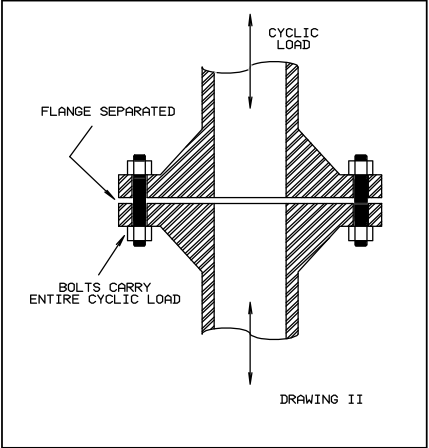
Nnow let us have a look at the mechanics of why bolts fail if flanges are allowed to separate during operation. In the figure below we can see a (somewhat exaggerated) flat faced flange connection like that which would be used in a cyclic loaded strut member. The same type joint is typically used when a compressor or power cylinder is mounted to the crankcase of large stationary equipment.
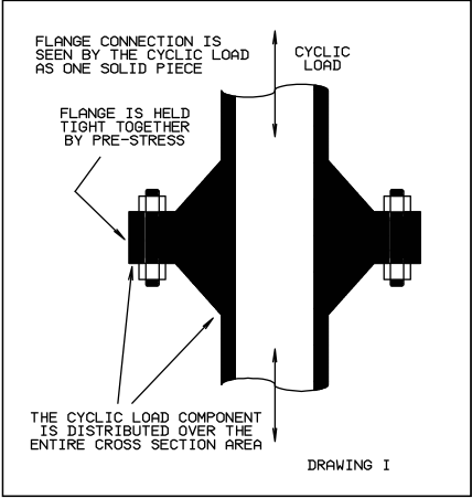
When held tightly together, the flange surfaces effectively act as a single, solid piece when cyclic stress is applied. This is because the cyclic component is distributed over the entire area, meaning that the bolts only see a small part of the total stresses being applied in relation to their cross sectional area. In the case of the bolt shown in the figure above, that would be about four percent.
The protected condition requires that the pretension on the bolts be high enough to hold the flange tightly together under the cyclic loading. If the pretension be too low, the flange faces will separate during at least part of the loading cycle, as shown in the figure below. Under this condition, the full cyclic load must be born by the bolts, which will cause them to become subject to cyclic stress and fatigue.
Finally, we'll look at a method that can lower the bolt’s susceptibility to flange separation. It involves dealing with the rigidity of the bolt and it's stress concentration factor. the figure below shows two typical flange stud bolts, each being of equal strength for steady loading, but the one with reduced mid section being stronger for cyclic loading.
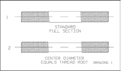
The effective load bearing cross section for a bolt is the root diameter of the threaded area. The second bolt has the same effective cross section as the first, even though the center portion has been machined down to the root diameter. So, for steady loading, the two bolts are essentially the same.
The stress concentration factor for cyclic loading, however, is reduced by the reduced stiffness. At the same time, the reduced bolt is less likely to become loose with occasional thermal changes because it has more spring action. The best combination of reduction in stress concentration and improved spring action is accomplished with the mid portion reduced to roughly 15% below the thread root.
Hopefully you found this information helpful. Bolt integrity is an integral part of every plant and facility, so maintaining the health of the bolts that hold a plant together is of utmost importance to the overall health of a facility.


Comments and Discussion
There are no comments yet.
Add a Comment
Please log in or register to participate in comments and discussions.