Introduction
This article provides a discussion of a recent inspection performed at a U.S. refinery. Industry HF lines are experiencing piping failures in increasing numbers due to the presence of residual elements (such as Cr, Ni, and Cu among others) entrained within their carbon steel components. Because of this, a non-destructive testing (NDT) inspection program was developed to identify and quantify this highly localized corrosion in carbon steel piping, along with assessing for damage in butt joints between different piping sections.
After identifying the welds in drawings, the following examinations were performed:
- Guided wave testing (GWT) to identify the line welds (transverse to the pipe)
- Real-time radiography (RTR) to pin-point, without removing insulation, the locations of some transverse joints requiring computed radiography (CR)
- Computed radiography (CR) to:
- Quantify erosion/corrosion losses in suspect welds of NPS less or equal to 6,
- And rank, based on density changes, thinning of pipe of NPS greater than 6 operating at temperatures greater than 200 °F, and
- Creeping wave manual ultrasound testing (MUT) to scan welds of NPS greater than 6
The primary objective of all of these examinations was to ensure that all welds and components were captured during the inspection effort. Most of the inspections were performed as the lines were in service, in order to avoid the congestions usually associated with shutdowns. Once all the lines at ground level were examined, the remaining lines were inspected using rope access. Insulated and uninsulated lines, with diameters ranging from NPS 3/4 to NPS 24, were examined.
This article presents GWT and CR graphic information of the examinations. The CR images show weld attack and attack to threaded joints. Detailed metallographic examination results of the damage to one of the deficient joints removed from service are shown.
Examinations
Preliminary
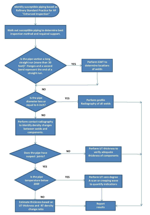
Prior to performing NDT examinations piping circuit lists were created, weld locations were identified based on drawings, and on longer runs of piping, with GWT, and inspection personnel walked down the lines. The NDT techniques for each joint were chosen based on the specific piping configuration, as illustrated in Figure 2.
Guided Wave Testing (GWT)
GWT was used to identify the location of welds in straight run piping sections longer than 30’. To perform this type of inspection, a small amount of insulation is removed and a transducer ring is clamped around the pipe. This transducer transmits guided waves in both directions along the pipe. The signals reflected from pipe features such as welds are received by the transducer ring and recorded.
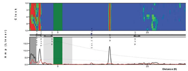
Flanges and “second” bends mark the extent of data collected without relocating the ring. Welds create a symmetric reflection proportional to the change in cross sectional area and reflect 20 - 25% or more of the GWT signal. Weld signals are illustrated in Figure 3.
Read Related Articles
Creeping Wave MUT
This type of examination is performed in carbon steel, stainless steel and nickel stainless alloys. In this case, it was used to examine piping welds with NPS larger than 6, operating at temperatures below 200 °F suspected of having localized losses. For these examinations, an ID creeping wave is generated that follows the ID surface. Welds with no weld root erosion return little or no signal to the transducer. In contrast, welds with erosion return a creeping wave signal.
Profile Radiographic Testing (RT) and Computed Radiography (CR)
For this examination, the pipe was exposed to radiation from an iridium gamma source. This allowed the wall thickness to be measured at the pipe edges of pipe with diameters of NPS 6 and less. Flexible imaging plates were used to obtain digital radiographs for CR. This allowed us to examine images with extensive latitude where the contrast could be modified and the brightness optimized. Film was used in conventional RT due to equipment/personnel availability for a small fraction of the joints examined.
For pipe diameters of NPS 6 or less, the radiographs were obtained with a standard profile configuration (superimposed exposures). The wall thickness was measured at the edges. For these lines, the piping was shot with insulation.
For pipe diameters greater than NPS 6, the images obtained were “contact shots”. This allowed for the shot time to be reduced for operating lines. The wall thickness was not measured with this type of exposure. The insulation had to be removed to shoot the larger diameter lines.
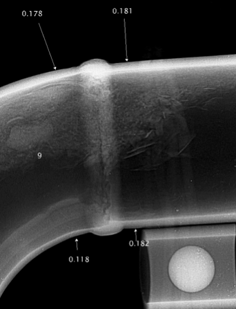
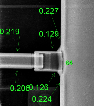
The lines had highly localized losses in the DWM, piping and threaded components. Some of these losses are illustrated in Figures 4 and 5.
Real Time Radiography (RTR)
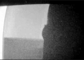
This process was performed to pin-point, without removing insulation, at the locations of some transverse joints requiring computed radiography (CR). For RTR weld mapping a real time video x-ray system, known as a C-arm, directs radiation toward a digital detector array (DDA). This radiation penetrates the cladding and insulation, but not the pipe wall. The outside surface of the pipe and its welds can be seen clearly. The C-arm was manipulated around the pipe to image the OD of the welds. The information obtained from the examination is illustrated in Figure 6.
Rope Access
Once all ground level and easily accessible lines were inspected, the remaining inspections were performed by personnel using rope access.
Examinations of Attacked Reducer Rejected with CR
1. Visual Examination
The reducer was removed from a low acid strength isobutane side draw line from the main fractionator. The remaining steel surfaces in attacked areas were rough. Those surfaces with variable topographies were consistent with the blurred through thickness profile in the CR images. The thickness of the pipe was of the order of 0.295 inch. Instead, the thickness of the reducer was as low as 0.05 inch.
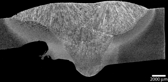
2. Metallographic Examination
The parent metal losses are greatest in the reducer, next to the deposited weld metal (DWM). As shown in Figure 7, some of the reducer side heat affected zone (HAZ) has also been attacked. The pipe side HAZ and the weld root appear to be free of attack.
3. Hardness Tests
Vickers HV10/15 hardness measurements were made on the polished cross-sections. The values are somewhat high for post weld heat treated welds. However, the HAZ values are below the 248 HV specified to avert hydrogen stress cracking.
4. Chemical Analysis
The chemical composition of the reducer, piping sections and DWM between the pipe and reducer were examined with optical emission spectroscopy (OES, “Spark”). The results are summarized below.
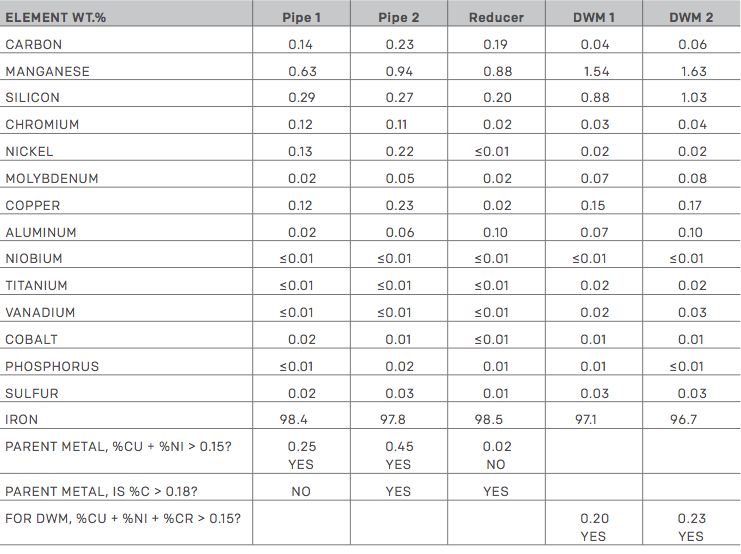
The reducer had lower residual elements (RE) than the piping and welds with which it was galvanically coupled.
Summary
CR of the NPS 4 to NPS 24 carbon steel effectively identified losses in the HF line components. GWT, RTR and UT gave useful complementary information to focus the RT and CR examinations. Rope access technologies also facilitated completing the inspections.
One of the attacked reducers identified with RT was examined destructively. The reducer had had pipe sections joined on each end. The two pipe sections and the DWM on each side had higher RE than the reducer. The reducer losses occurred next to the welds; some of the reducer side HAZ had also been attacked. The pipe side HAZ and the weld root were free of attack. This preferential attack of low RE steel coupled to high RE steel has been reported for low acid strength lines.
References
- Munsterman, T., and Mayorga, A., September 2004, “Preferential Corrosion of Welds in HF Service,” Hydrocarbon Processing, pp. 113–119.
- Gysbers, A., et al., 2003, “Specification for Carbon Steel Materials for Hydrofluoric Acid Alkylation Units,” NACE International Paper No. 03651.
© 2015 Marathon Petroleum Company LP


Comments and Discussion
Add a Comment
Please log in or register to participate in comments and discussions.